Combustor inlet diffuser with boundary layer blowing

a technology of boundary layer blowing and combustor, which is applied in the direction of machines/engines, liquid fuel engines, lighting and heating apparatus, etc., can solve the problems of affecting performance and stall margin, placing additional constraints on design, and higher diffusion rates, so as to reduce engine length, weight and cost, the effect of preventing flow separation

Inactive Publication Date: 2005-01-18
GENERAL ELECTRIC CO
View PDF15 Cites 26 Cited by
  • Summary
  • Abstract
  • Description
  • Claims
  • Application Information

AI Technical Summary

Benefits of technology

The invention provides a gas turbine engine design that reduces the axial length of the diffuser. The invention reduces engine length, weight, and cost by preventing flow separation along the annular walls of the diffuser while maintaining acceptable levels of engine performance and stall margin.

Problems solved by technology

Some engine configurations also require the OGVs to serve as a structural member which places additional constraints on the design.
Reduced length typically results in higher diffusion rates which makes the boundary layers more susceptible to separation which negatively impact performance and stall margin.
Thus, reduced length and high diffusion rates tend to be conflicting requirements.
Conventional combustor inlet diffusers, designed for these conditions, have high pressure losses, which would cause a considerable increase in engine specific fuel consumption.
A very long conventional diffuser may recover as much as one-half of this velocity head, but the pressure losses would still be high and the engine would be considerably longer and heavier.
Some of this flow could be used for turbine cooling, but at this point in the engine cycle, the pressure is considerably lower than the compressor exit pressure, which would result in sizable pressure losses for the bleed flow.

Method used


Image

  • Combustor inlet diffuser with boundary layer blowing
  • Combustor inlet diffuser with boundary layer blowing
  • Combustor inlet diffuser with boundary layer blowing

Examples


Embodiment Construction

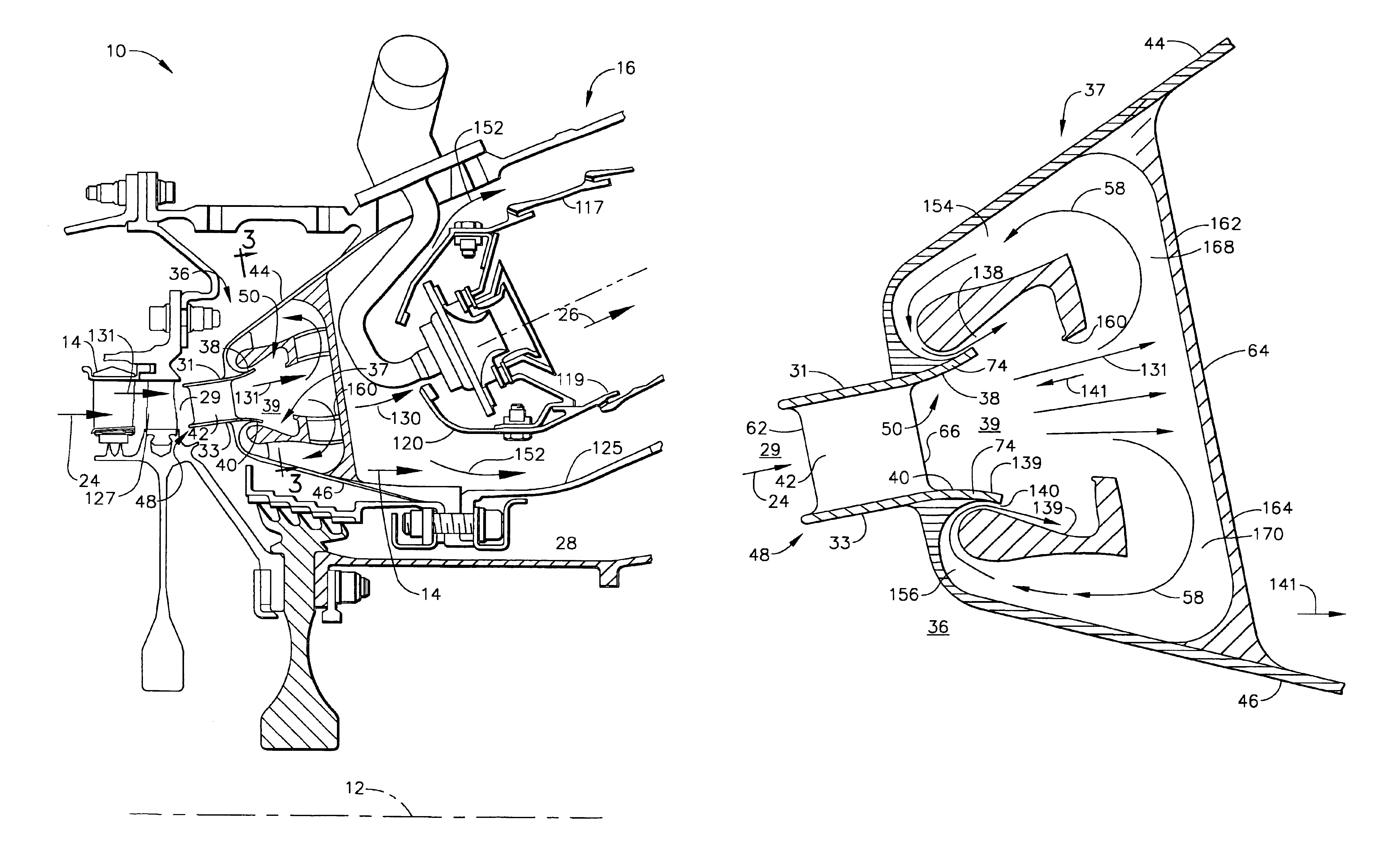
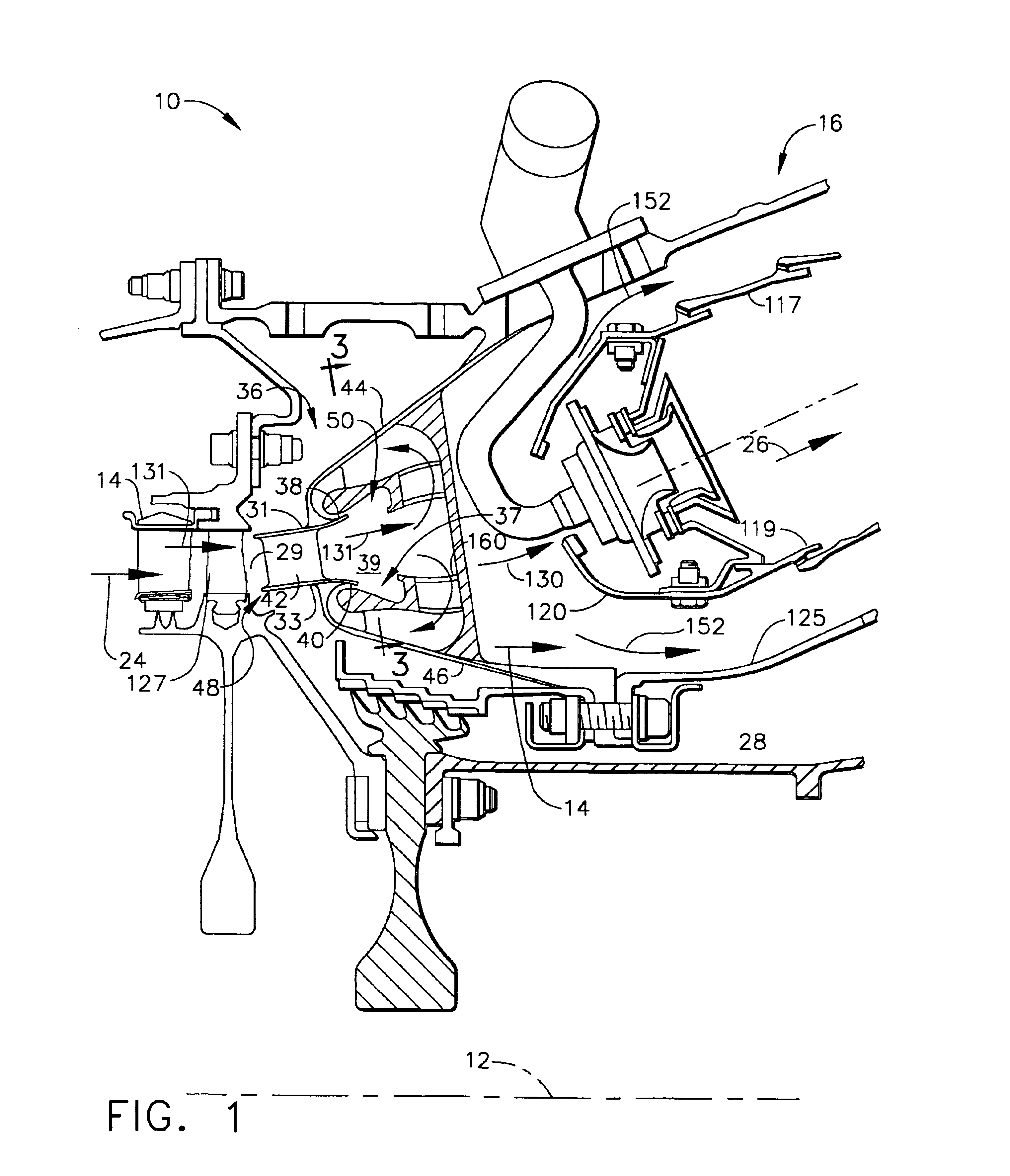
Illustrated in FIG. 1 is a portion of a gas turbine engine 10 including in serial flow communication about an axial centerline axis 12 conventional annular and axisymmetric structures including an axial flow compressor 14 and a combustor 16. The compressor 14 receives inlet airflow and compresses it into relatively hot compressed airflow 24 which is flowed through a gas turbine engine outlet guide vane and diffuser assembly 36 to the combustor 16 in which it is conventionally mixed with fuel and ignited for generating combustion gases 26. The gases 26 are flowed into a turbine (not shown) which extracts energy therefrom for rotating the turbine, which in turn, rotates and powers the compressor 14 through a shaft 28.

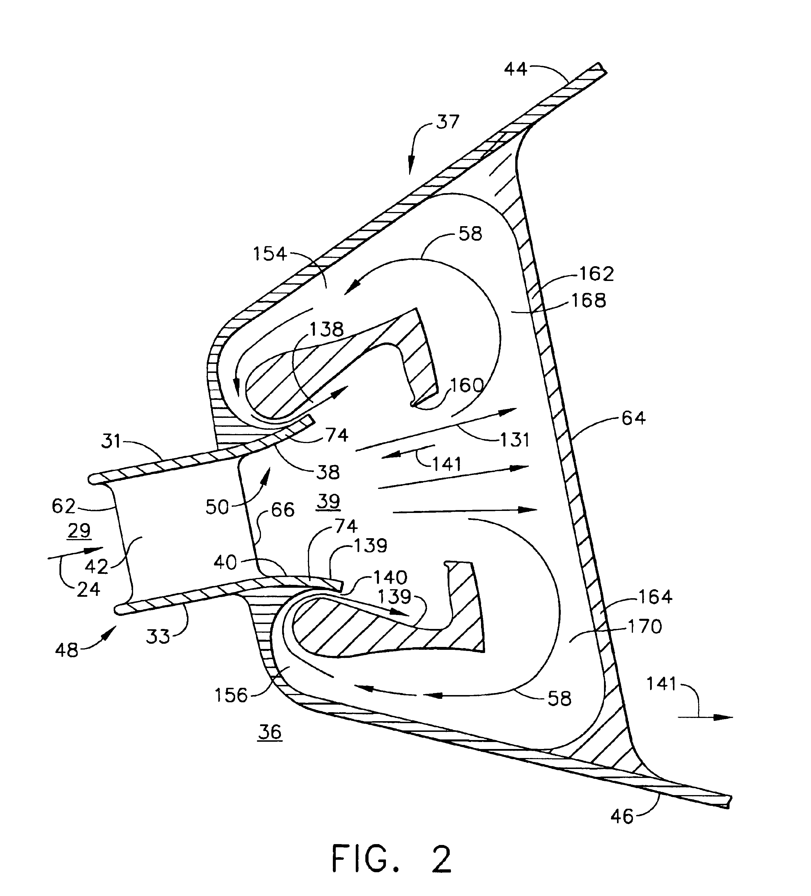
The outlet guide vane and diffuser assembly 36 has integral outlet guide vane section 48 and a combustor inlet diffuser 50. The outlet guide vane section is located forward or upstream of the diffuser 50. The outlet guide vane section 48 includes a plurality of circumfere...


PUM


Abstract

A gas turbine engine combustor inlet diffuser assembly has at least one diverging annular wall including a flowpath surface bounding a diffuser flowpath. An annular blowing slot is axially located along the annular wall and an annular blowing air flowpath leads to and is in fluid communication with the blowing slot. An annular array of scoops disposed in the diffuser flowpath downstream of the blowing slot have upstream facing openings and are in fluid communication with the blowing air flowpath. The annular scoops are supported on hollow struts. Each of the hollow struts has at least one radially extending flow passage for directing blowing air from the scoop to the blowing air flowpath. The blowing slot opens in a downstream direction with respect to the diffuser flowpath. A row of blowing air compressor blades disposed across the blowing air flowpath may be used to pump up the pressure of the blowing air.

Description

BACKGROUND OF THE INVENTION1. Field of the InventionThe present invention relates generally to gas turbine engine combustor inlet diffusers and, more specifically, to blowing air into boundary layers of annular walls surrounding diffuser flowpath.2. Background ArtA conventional gas turbine engine includes in serial flow communication, a compressor, a discharge flowpath having a stage of inlet compressor outlet guide vanes (OGVs), disposed between annular inner and outer walls, which in turn are mounted in an OGV support structure mechanically tied into an engine casing. Outlet guide vanes typically have airfoil like cross-sections that include a leading edge, a relatively thick middle section, and a thin trailing edge. Downstream of the OGVs is a combustor inlet diffuser, a combustor, a turbine nozzle, and a high pressure turbine. Typically, OGV inner and outer walls are supported by corresponding inner and outer annular diffuser inlet walls to form a relatively leak-free flowpath t...

Claims


Application Information

Patent Timeline
Patent Type & Authority Patents(United States)
IPC IPC(8): F04D29/68F04D29/66F23R3/02F23R3/10F23R3/04F23R3/26F23R3/16
CPCF04D29/681F23R3/26F23R3/10Y02T50/675F04D29/684F04D25/16F04D29/542F04D29/545Y02T50/60
Inventor BURRUS, DAVID LOUISTAYLOR, JACK ROGERS
Owner GENERAL ELECTRIC CO
Why Eureka
Try Eureka