Fluid-aligned measurement apparatus and method

a measurement apparatus and fluid-tightness technology, applied in the direction of fluid-tightness measurement, instruments, digital computer details, etc., can solve the problems of poor fluid-tightness measurement, reduced fuel economy, and power loss

Inactive Publication Date: 2005-01-18
PETERSON ROBERT +2
View PDF20 Cites 4 Cited by
  • Summary
  • Abstract
  • Description
  • Claims
  • Application Information

AI Technical Summary

Benefits of technology

Therefore, it is an object of the present invention to produce one or more characterizing measurements of a surface in relation to a repeatedly reproducible datum axis, based on a probe that utilizes a non-contacting fluid pressure gap at both the first and second porous surfaces. Additional objects of the present invention include: obtaining characterizing measurements without having a measurement device touch the surface to be measured; having a plurality of second porous surfaces being located on a plurality of arms extending radially from the probe; having a second porous surface being located on a plug extending radially along the entire perimeter of the probe; having a drive assembly for rotating the probe about the datum axis; having a microprocessor for generating a signal in response to the characterizing measurements; having a calibration device for calibrating the probe; having a regulator to supply each porous surface with different levels of fluid pressure; having a template that permits registration of the apparatus in relation to the surface to be measured; having an air-bearing that provides a flotational means of allowing the probe to align in relation to the walls; having radial displacement transducers that extend radially from the probe with a porous surface located on the distal end thereof; having an transducer for recording displacement of the probe; having the first and second porous surfaces adjustably fitted with a surface that corresponds to the surface geometry of the surface to be measured; and means for communicating the measurements in real time.

Problems solved by technology

When the valve head does not properly fit in the valve seat, the intake passage and the exhaust passage will riot be sealed properly during the compression and power strokes, thus causing power loss, reduced fuel economy, rough engine idling and increased pollution.
Poor sealing also reduces the valve head and valve seat life by allowing hot exhaust gasses to leak and contact the valve surfaces and the valve seats.
Pierce lacks the ability to repeatedly reproduce the datum axis using a non-contacting fluid pressure gap.

Method used


Image

  • Fluid-aligned measurement apparatus and method
  • Fluid-aligned measurement apparatus and method
  • Fluid-aligned measurement apparatus and method

Examples


Embodiment Construction

This invention pertains to an apparatus for producing one or more characterizing measurements of a surface in relation to a repeatedly reproducible datum axis. The following exemplary modes for carrying out the invention relate to producing characterizing measurements of concentricity, ovality, waviness, and out-of-plane of a combustion chamber's valve seat in relation to a valve guide cavity. However, as one ordinarily skilled in the art will realize, the present invention may be used in additional automotive and non-automotive applications where similar measurements are useful.

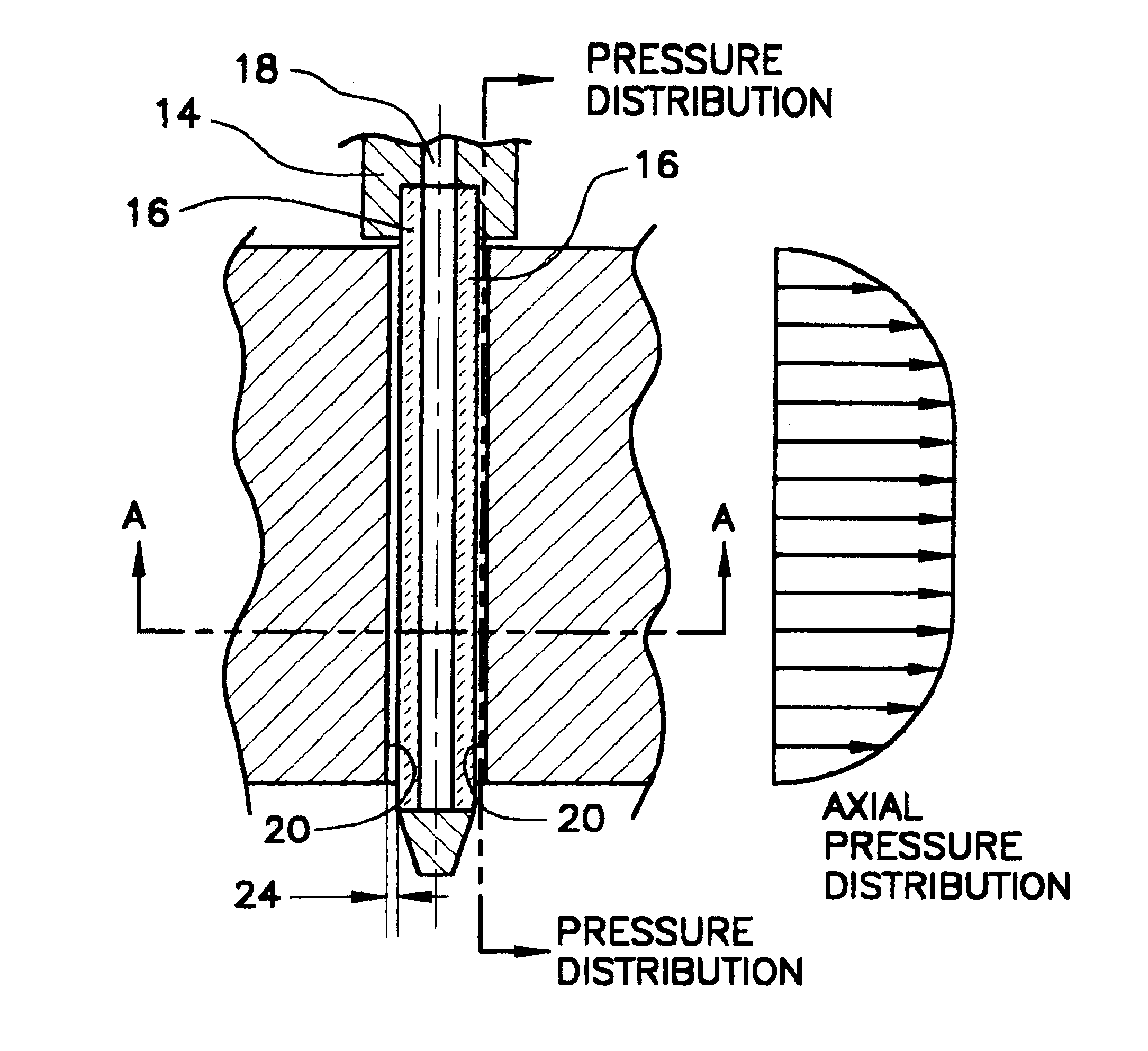
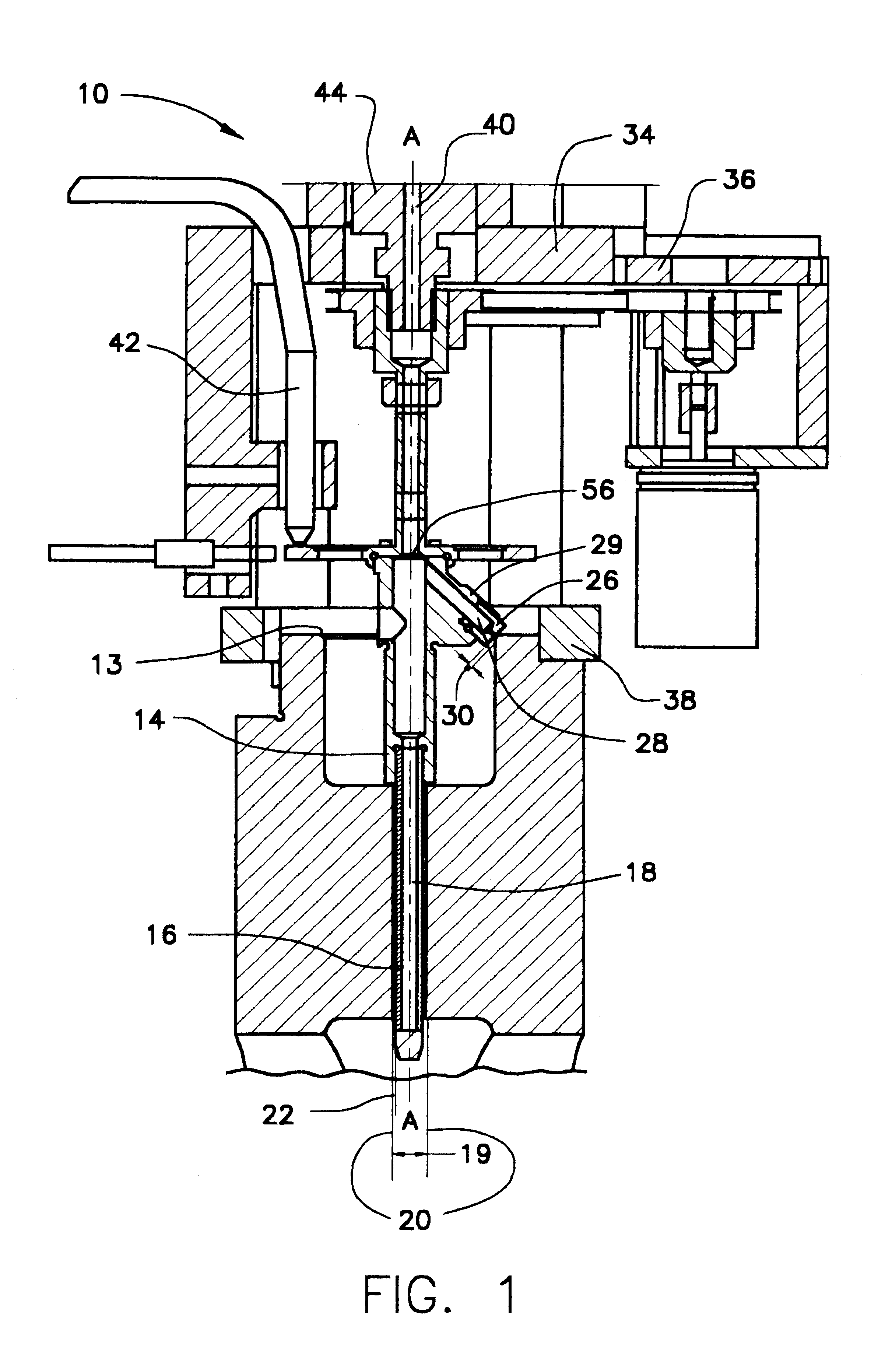
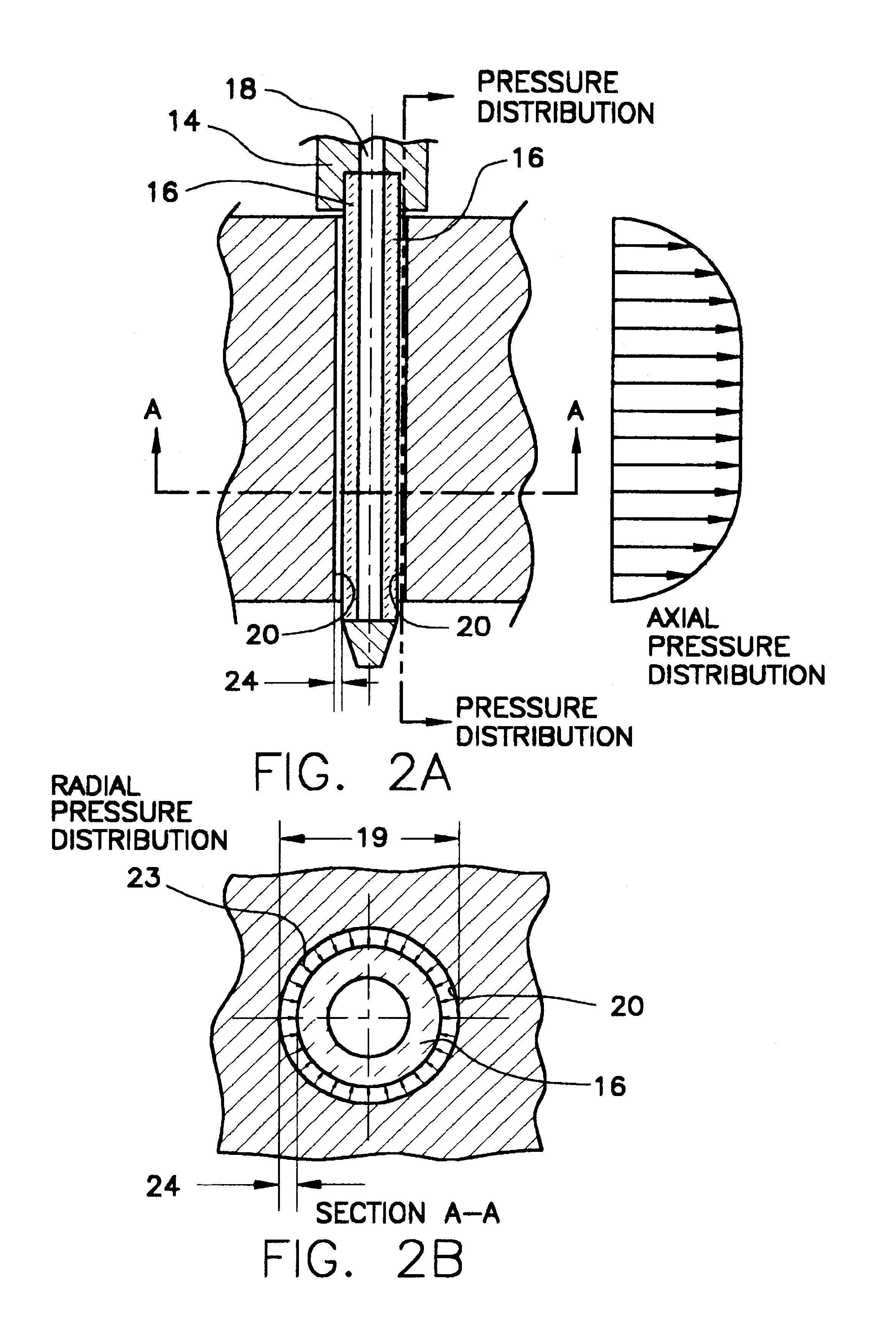
FIG. 1 illustrates the preferred embodiment of an apparatus 10 for performing characterizing measurements of a valve seat surface 13 in relation to a repeatedly reproducible datum axis A-A. Located on the outer surface of the leading insertion end of a probe 14 is a first porous surface 16 that communicates with a source of first fluid pressure 18. The first porous surface 16 has a diameter sufficiently less...


PUM


Abstract

An apparatus 10 for producing one or more characterizing measurements of a surface 12 in relation to a repeatedly reproducible datum axis A-A, the apparatus 10 comprising a probe 14; a first porous surface 16 located on the probe 14, the first porous surface 16 being in communication with a first source of fluid pressure 18, the first porous surface 16 being located proximate to opposing walls 20 that defines a volume 22, so that a non-contacting fluid pressure gap 24 is formed between the first porous surface 16 and the walls 20, the first porous surface 16 defining the datum axis A-A; at least one second porous surface 26 located on the probe 14, the at least one second porous surface 26 being in communication with a second source of fluid pressure 28, the at least one second porous surface 26 being located in a cooperative relationship with the surface 12 to be measured, so that a non-contacting fluid pressure gap 30 is fanned between the at least one second porous surface 26 and the surface to be measured; and means for generating one or more characterizing measurements of the surface to be measured in relation to the datum axis.

Description

FIELD OF THE INVENTIONThis invention relates to an apparatus for producing one or more characterizing measurements of a surface in relation to a repeatedly reproducible Datum axis.BACKGROUND OF THE INVENTIONConcentricity, ovality, waviness, and out-of-plane features characterize a geometric surface. Such characterizing features are used in a number of applications; one in particular involves measuring a valve seat relative to a valve guide cavity of an engine's combustion chamber. Wherein, a valve reciprocates in the valve guide to open and close intake and exhaust passages, which communicate with engine cylinders. The valve seat is a tapered surface that facilitates seating the valve head in the intake and exhaust passages from the cylinders during the compression and power strokes of the engine.When the valve head does not properly fit in the valve seat, the intake passage and the exhaust passage will riot be sealed properly during the compression and power strokes, thus causing p...

Claims


Application Information

Patent Timeline
Patent Type & Authority Patents(United States)
IPC IPC(8): G01M13/00
CPCG01M13/00
Inventor PETERSON, ROBERTHOBSON, JAMES C.NOVIKOV, MIKHAIL V.
Owner PETERSON ROBERT
Why Eureka
Try Eureka