Internal combustion engine and control method of the same

Inactive Publication Date: 2005-01-18
TOYOTA JIDOSHA KK
View PDF11 Cites 7 Cited by
  • Summary
  • Abstract
  • Description
  • Claims
  • Application Information

AI Technical Summary

Benefits of technology

The invention is made in view of the foregoing problems, and it is an object of the invention to prevent degradation in the exhaust emission and to enable early activation of an exhaust purifying catalyst using a technique capable of optimally controlling the air-fuel ratio and / or the ignition timing of the internal combustion engine that is preheated before or upon starting.
In this case, combustion energy of the internal combustion engine is increased as the intake air amount increases. Accordingly, unnecessary reduction in the engine speed is reduced even when increasing the air-fuel ratio is increased and / or the degree of retarding the ignition timing are amount of the ignition timing.

Problems solved by technology

In the conventional heat-accumulating device for the engine as described above, however, the air-fuel ratio of the engine is not taken into account in the case of warm-up of the intake system and fuel supply system using hot cooling water stored in a heat-accumulating container.
As a result, a relatively large amount of unburned fuel components is discharged from the internal combustion engine, thereby possibly degrading the exhaust emission.
During the cold starting, however, combustion of the air-fuel mixture is likely to be unstable.
In this respect, a degree of retarding the ignition timing is limited.
Therefore, the degree of retarding the ignition timing may possibly be limited despite the fact that the ignition performance and combustion stability of the air-fuel mixture have been obtained by warming up the intake system and fuel supplying system.
If the degree of retarding the ignition timing is limited when the ignition performance and combustion stability of the air-fuel mixture have been compensated by warming up the intake system and fuel supply system, the exhaust temperature cannot be raised to a desired value.
As a result, it may take a long time to activate the exhaust purifying catalyst.

Method used


Image

  • Internal combustion engine and control method of the same
  • Internal combustion engine and control method of the same
  • Internal combustion engine and control method of the same

Examples


first embodiment

A first embodiment of the internal combustion engine according to the invention will now be described referring to FIGS. 1 to 5.

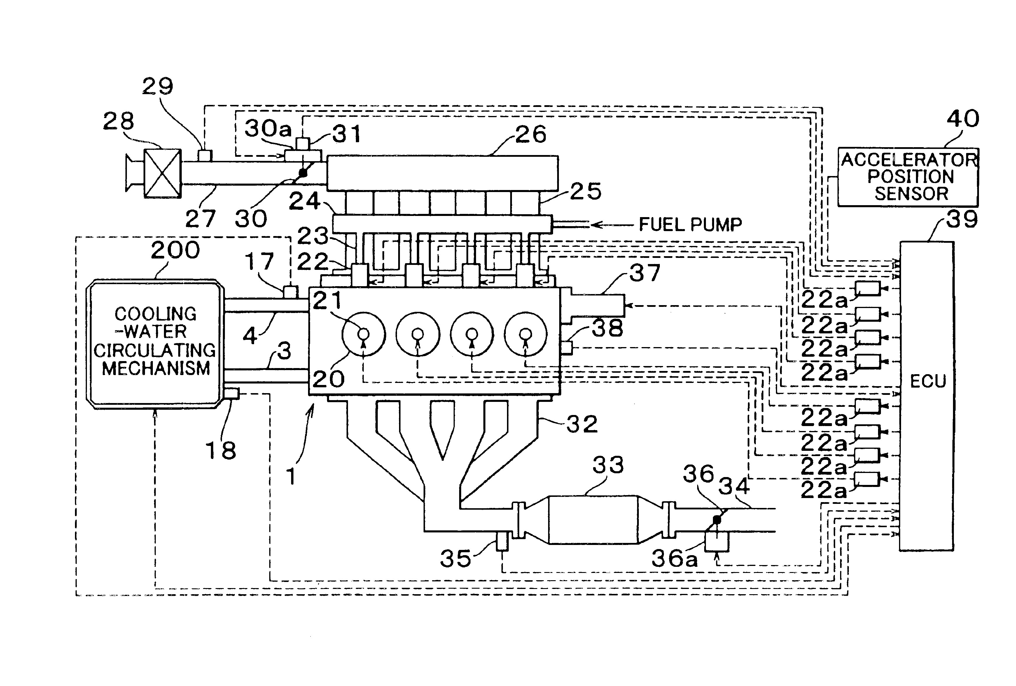
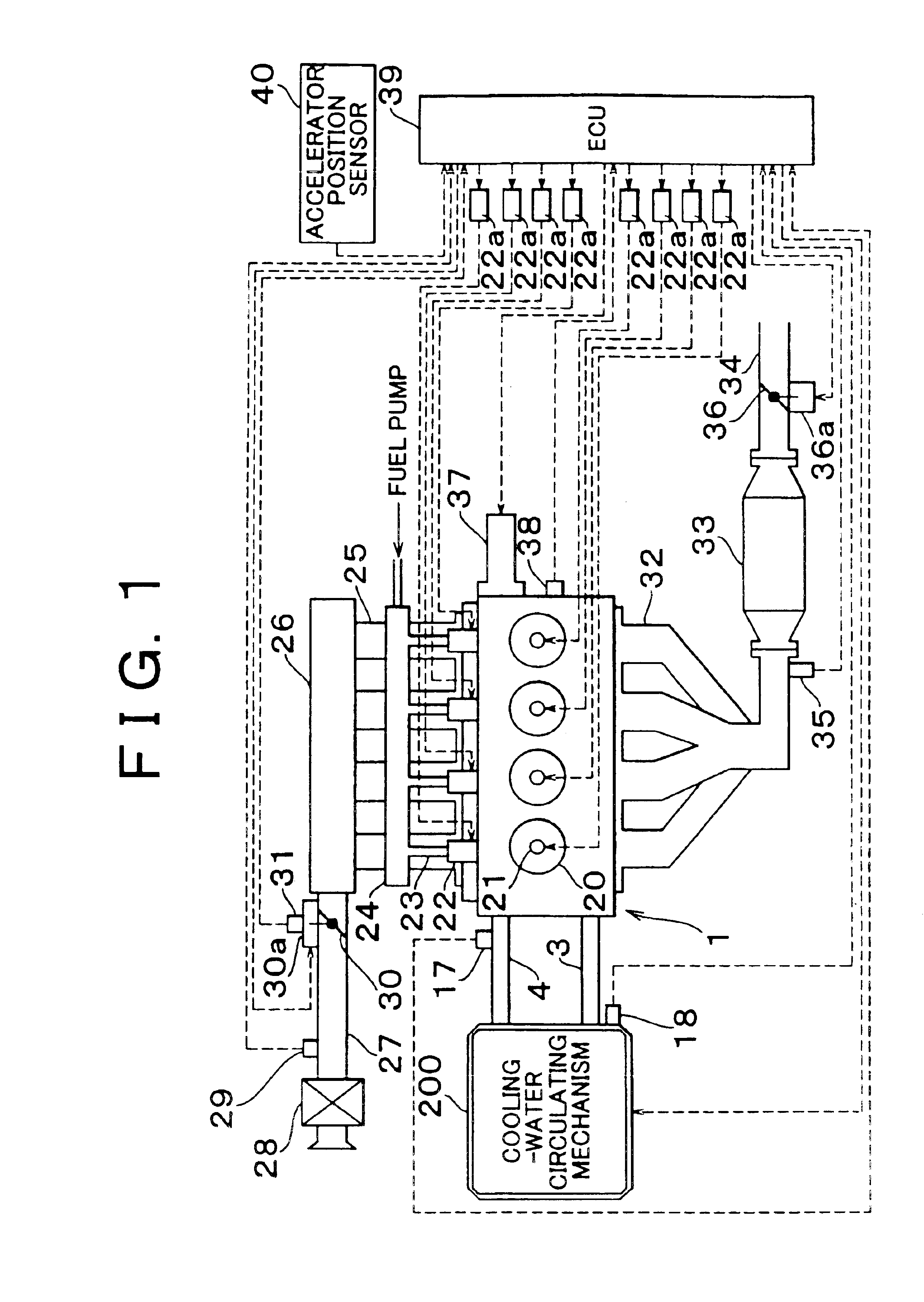
FIG. 1 is a diagram schematically showing the structure of the internal combustion engine according to the present embodiment.

The internal combustion engine 1 of FIG. 1 is a four-stroke cycle water-cooled gasoline engine including four cylinders 20.

The internal combustion engine 1 includes spark plugs 21 mounted so as to face combustion chambers of the respective cylinders 20. Igniters 21a are electrically connected to the respective spark plugs 21 to which the driving electric power is supplied.

The internal combustion engine 1 includes a starter motor 37 for rotating an engine output shaft (crankshaft) of the internal combustion engine 1 in response to application of driving electric power, and a crank position sensor 38 for outputting a puls signal every rotation of the crankshaft at a predetermined angle (e.g., 10°).

The internal combustion engine 1 furth...
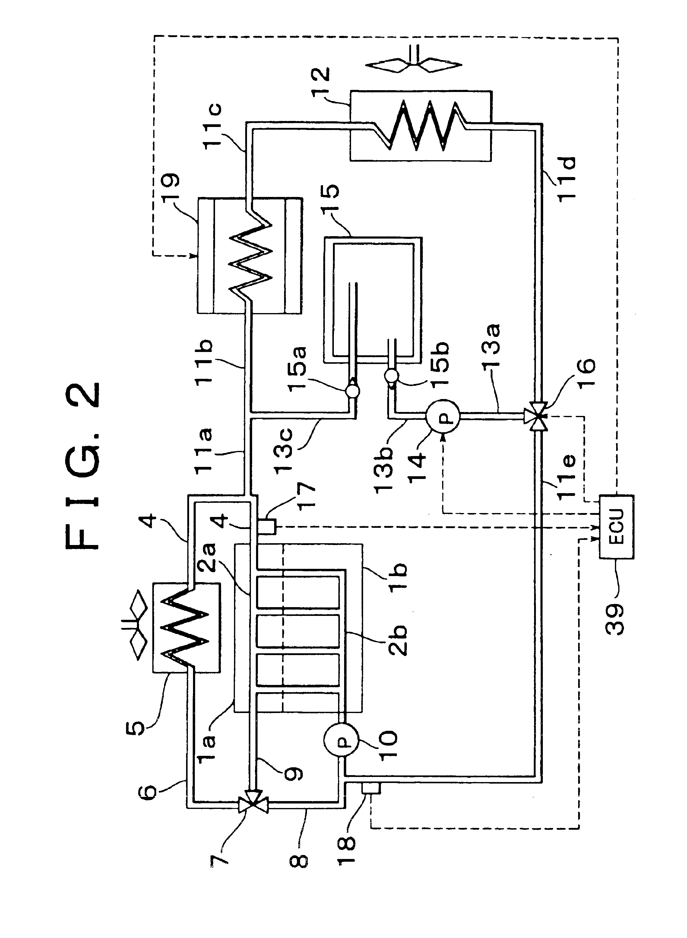
second embodiment

Hereinafter, a second embodiment of the internal combustion engine of the invention will be described in connection with FIG. 6. Only the structure different from that of the first embodiment will be described herein, and description of the same structure will be omitted.

According to the first embodiment, in the case where the internal combustion engine 1 is preheated before starting thereof, the air-fuel ratio upon and immediately after starting is set to a value higher than that in the case where the internal combustion engine 1 is not preheated. In the present embodiment, however, in the case where the internal combustion engine 1 is preheated, the ignition timing upon and immediately after starting is retarded as compared to the ignition timing of the internal combustion engine 1 that is not preheated.

Regarding early activation of the exhaust purifying catalyst 33, the following technique is known: when the exhaust purifying catalyst 33 is not activated as in the case where the ...


PUM


Abstract

The internal combustion engine includes an engine preheating apparatus for preheating the internal combustion engine upon or before starting thereof. This internal combustion engine further includes an air-fuel ratio controller for setting an air-fuel ratio of the internal combustion engine that is preheated, to a value higher than that of the internal combustion engine that is not preheated, and / or an ignition-timing controller for retarding an ignition timing of the internal combustion engine that is preheated as compared with the ignition timing of the internal combustion engine that is not preheated.

Description

The disclosure of Japanese Patent Application No. 2000-225923 filed on Jul. 26, 2000 including the specification, drawings and abstract is incorporated herein by reference in its entirety.BACKGROUND OF THE INVENTION1. Field of the InventionThe invention generally relates to an internal combustion engine mounted on a vehicle and the like. More particularly, the invention relates to an internal combustion engine preheated upon or before starting, and a control method of the same.2. Description of Related ArtIn recent years, an internal combustion engine mounted on an automobile and the like is required to improve startability upon cold starting, reduce fuel consumption, and improve exhaust emission.In response to these requirements, a heat-accumulating device for the engine as described in JP-A-6-185359 has been proposed. According to the disclosed heat-accumulating device, a water-cooled internal combustion engine includes a first cooling-water passage running through a cylinder bloc...

Claims


Application Information

Patent Timeline
IPC IPC(8): F02D37/02F02D37/00F01P11/14F01P11/20F02D41/06F02D41/14F02N17/00F02N17/06F02P5/15F01P3/20F01P7/16F02D43/00F02D45/00F02N19/10
CPCF01P11/20F02D37/02F02D41/1487F02N19/10F02P5/1506F02D41/062F01P2011/205Y02T10/46Y02T10/40
Inventor SUZUKI, MAKOTOARISAWA, KATUHIKOTABATA, MASAKAZU
Owner TOYOTA JIDOSHA KK
Why Eureka
Try Eureka