Form-error-cancelling mirror-support devices and related methods, and microlithography systems comprising same

Inactive Publication Date: 2005-01-18
NIKON CORP
View PDF7 Cites 8 Cited by
  • Summary
  • Abstract
  • Description
  • Claims
  • Application Information

AI Technical Summary

Benefits of technology

According to another aspect of the invention, methods are provided, in the context of an X-ray optical system comprising at least one X-ray-reflective mirror mounted to a mounting structure in an optical column, for reducing a form error of the mirror. An embodiment of such a method comprises measuring (e.g., by interferometry) a profile of a reflective surface of the mirror so as to determine a region on the reflective surface exhibiting a respective form error. In a subsequent step a mirror-side surface of the mirror is contacted with at least three mirror-support devices selected from the group consisting of pushing devices and pulling devices, wherein the at least three mirror-support devices con

Problems solved by technology

As active circuit elements in microelectronic devices have become progressively smaller, the diffraction-limitations of current optical microlithography systems have become increasingly burdensome.
Also, the reflectivity of X-radiation from most known materials is very low.
Thus, it currently is impossible to construct X-ray optical systems employing conventional refractive and reflective optical elements.
Unless each multilayer-coated mirror of the system produces a sufficiently small wavefront error of reflected light, obtaining a desired optical performance consistent with target design rules is impossible.
It is extremely difficult to manufacture a multilayer-coated mirror (especially an aspherical mirror) having this precision.
It also is extremely difficult to avoid mirror-surface deformations that arise from mounting the mirrors in an optical column.
Furthermore, no matter how high the precision with which a mirror is fabricated, the profile of the reflective surface of the mirror is never ideal; it always has some residual form error.
Mounting the mirrors to, for example, a rigid metal frame can cause significant changes to the respective profiles of the reflective surfaces, resulting in a larger than expected form error for the overall system.
Since the same compressive force is applied to the mirror side at each contact point by the respective support devices, local deformation (due to the limited

Method used


Image

  • Form-error-cancelling mirror-support devices and related methods, and microlithography systems comprising same
  • Form-error-cancelling mirror-support devices and related methods, and microlithography systems comprising same
  • Form-error-cancelling mirror-support devices and related methods, and microlithography systems comprising same

Examples


Example

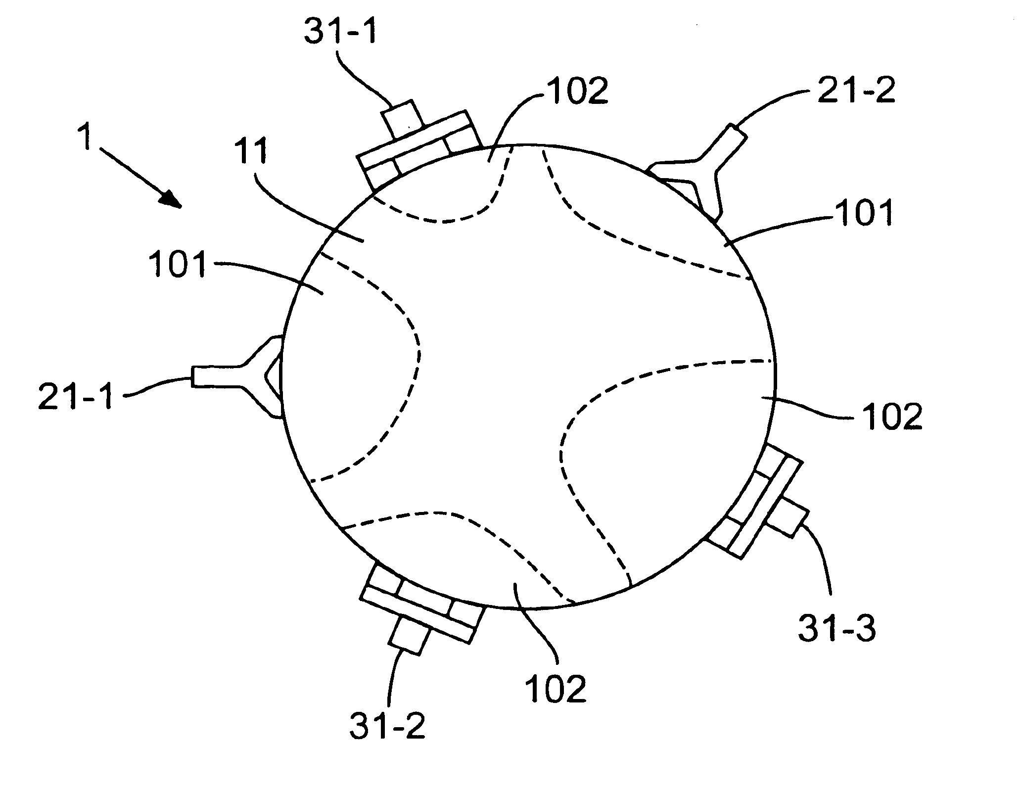
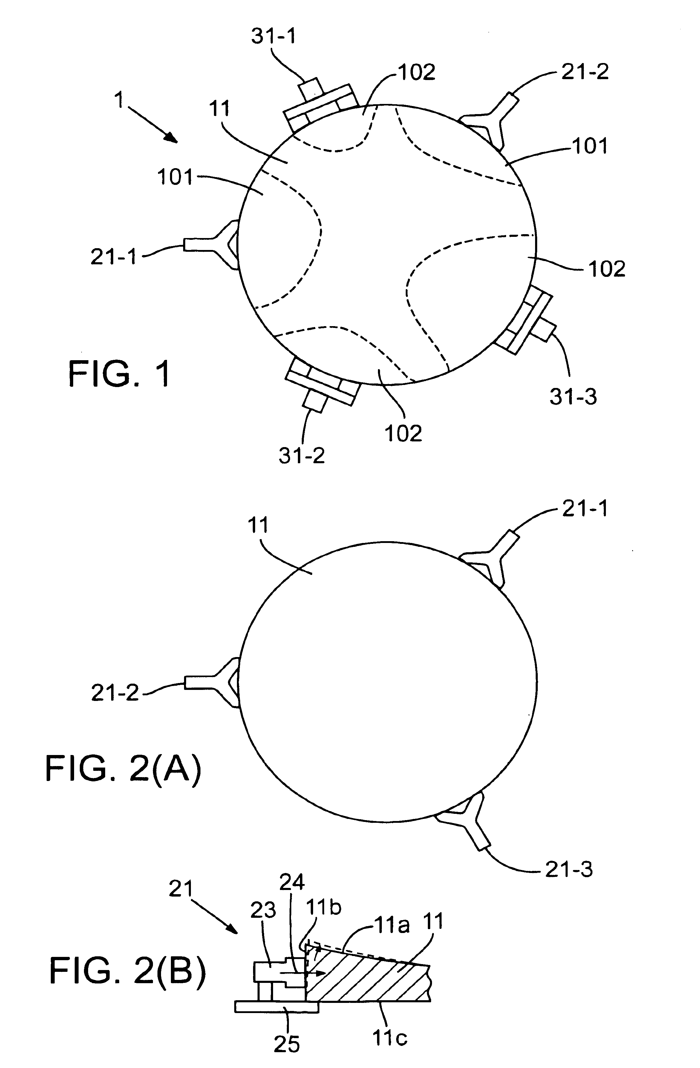
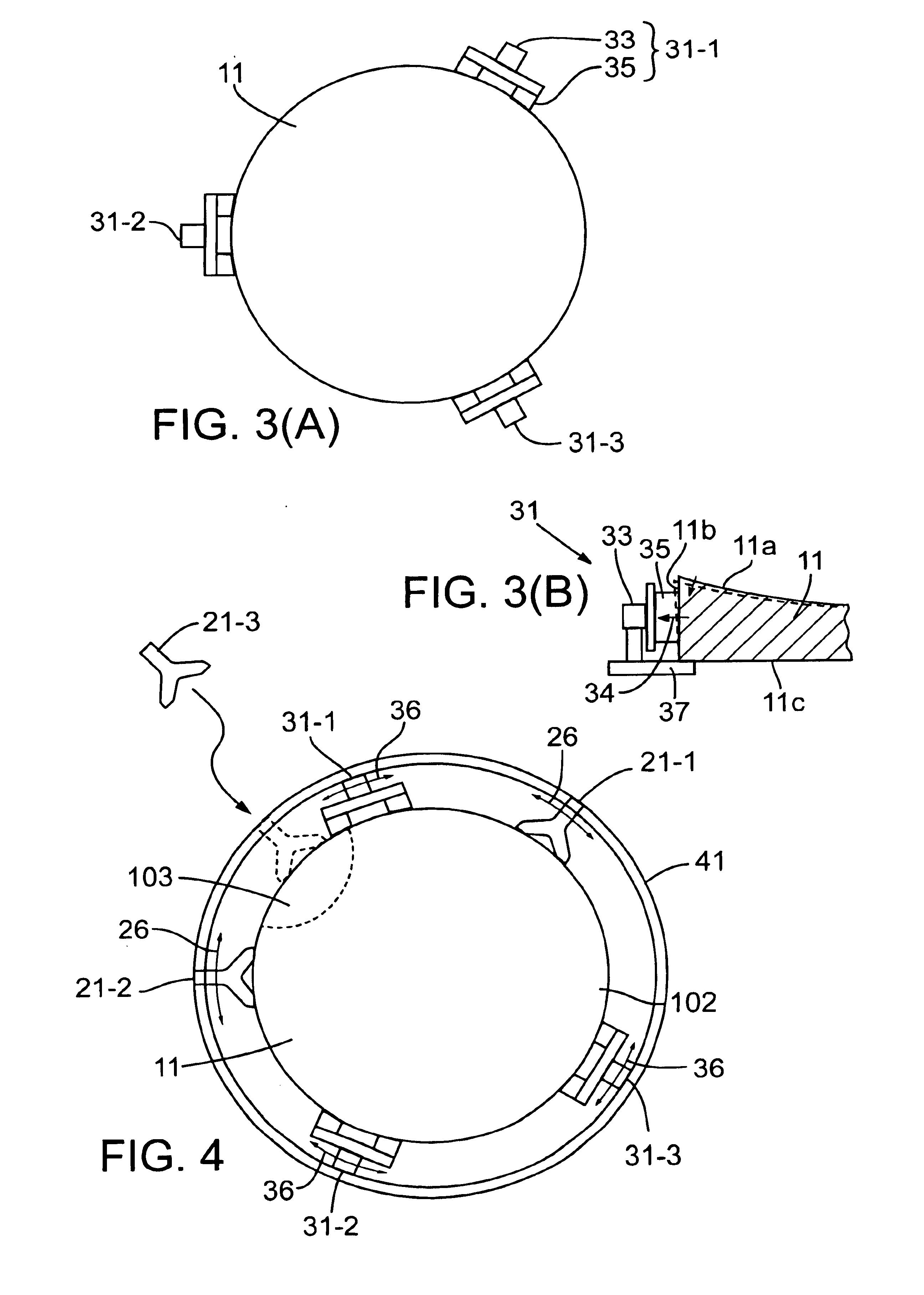
Various aspects of the invention are discussed below in the context of representative embodiments that are not intended to be limiting in any way.

First reference is made to FIG. 5, which depicts a SXR (EUV) projection-microlithography system 201 including one or more reflective optical components mounted as described later below. The system 201 of FIG. 5 employs, as a lithographic energy beam, a beam of EUV light of λ=13 nm. The depicted system 201 is configured to perform microlithographic exposures in a step-and-scan manner.

The EUV beam is produced by a laser-plasma source 207 excited by a laser 203 situated at the most upstream end of the depicted system 201. The laser 203 generates laser light at a wavelength within the range of near-infrared to visible. For example, the laser 203 can be a YAG laser or an excimer laser. Laser light emitted from the laser 203 is condensed by a condensing optical system 205 and directed to the downstream laser-plasma source 207. Upon receiving the...


PUM


Abstract

Methods and apparatus are disclosed for peripherally supporting X-ray-reflective mirrors such as used in X-ray microlithography systems and other X-ray optical systems. The methods provide effective physical support while reducing certain deformations in the reflective surface of the mirror. An embodiment of the method or mirror-support apparatus utilizes multiple “pushing” and “pushing” devices that apply a compressive stress and tensile stress, respectively, to respective locations on the peripheral-side surface of the mirror. One or more pushing devices and one or more pulling devices can be used as required. For example, at time of mirror fabrication, respective pushing devices can be placed adjacent concave-deviation regions and respective pulling devices can be placed adjacent convex-deviation regions on the reflective surface of the mirror. (Each pushing device produces an offsetting convexity in the adjacent mirror material, and each pulling device produces a corresponding concavity in the adjacent mirror material.) Thus, form errors arising at fabrication time are offset while simultaneously supporting the mirror.

Description

FIELDThis disclosure pertains to X-ray optical systems and to X-ray microlithography systems comprising same. “X-ray” encompasses not only the usual “hard” X-ray wavelengths but also the so-called “soft-X-ray” (SXR) wavelengths (including the so-called “extreme ultraviolet” (EUV) wavelengths). Microlithography is a key technology utilized in the fabrication of microelectronic devices such as integrated circuits and displays. More specifically, the disclosure pertains to X-ray-reflective mirrors as used in such optical systems, and to methods and apparatus for supporting such mirrors in an optical system.BACKGROUNDThe following summary is set forth, by way of example, in the context of a “soft-X-ray” (SXR) microlithography system as an exemplary X-ray optical system.As active circuit elements in microelectronic devices have become progressively smaller, the diffraction-limitations of current optical microlithography systems have become increasingly burdensome. Consequently, a large e...

Claims


Application Information

Patent Timeline
IPC IPC(8): G02B26/06G02B26/00G03F7/20G02B7/182G02B7/198H01L21/027
CPCG02B7/182G03F7/70825G03F7/70233G02B26/06
Inventor SHIRAISHI, MASAYUKI
Owner NIKON CORP
Why Eureka
Try Eureka