Cathode current control system for a wafer electroplating apparatus

a control system and electroplating technology, applied in the direction of electric circuits, manufacturing tools, electric circuits, etc., can solve the problems of negative electrodes, unstable, sulfate ions,

Inactive Publication Date: 2005-01-18
SEMITOOL INC
View PDF20 Cites 24 Cited by
  • Summary
  • Abstract
  • Description
  • Claims
  • Application Information

AI Technical Summary

Problems solved by technology

The sulfate ions, when discharged at the positive electrode, are unstable and combine with the water of the solution to form sulfuric acid and oxygen.

Method used


Image

  • Cathode current control system for a wafer electroplating apparatus
  • Cathode current control system for a wafer electroplating apparatus
  • Cathode current control system for a wafer electroplating apparatus

Examples


Embodiment Construction

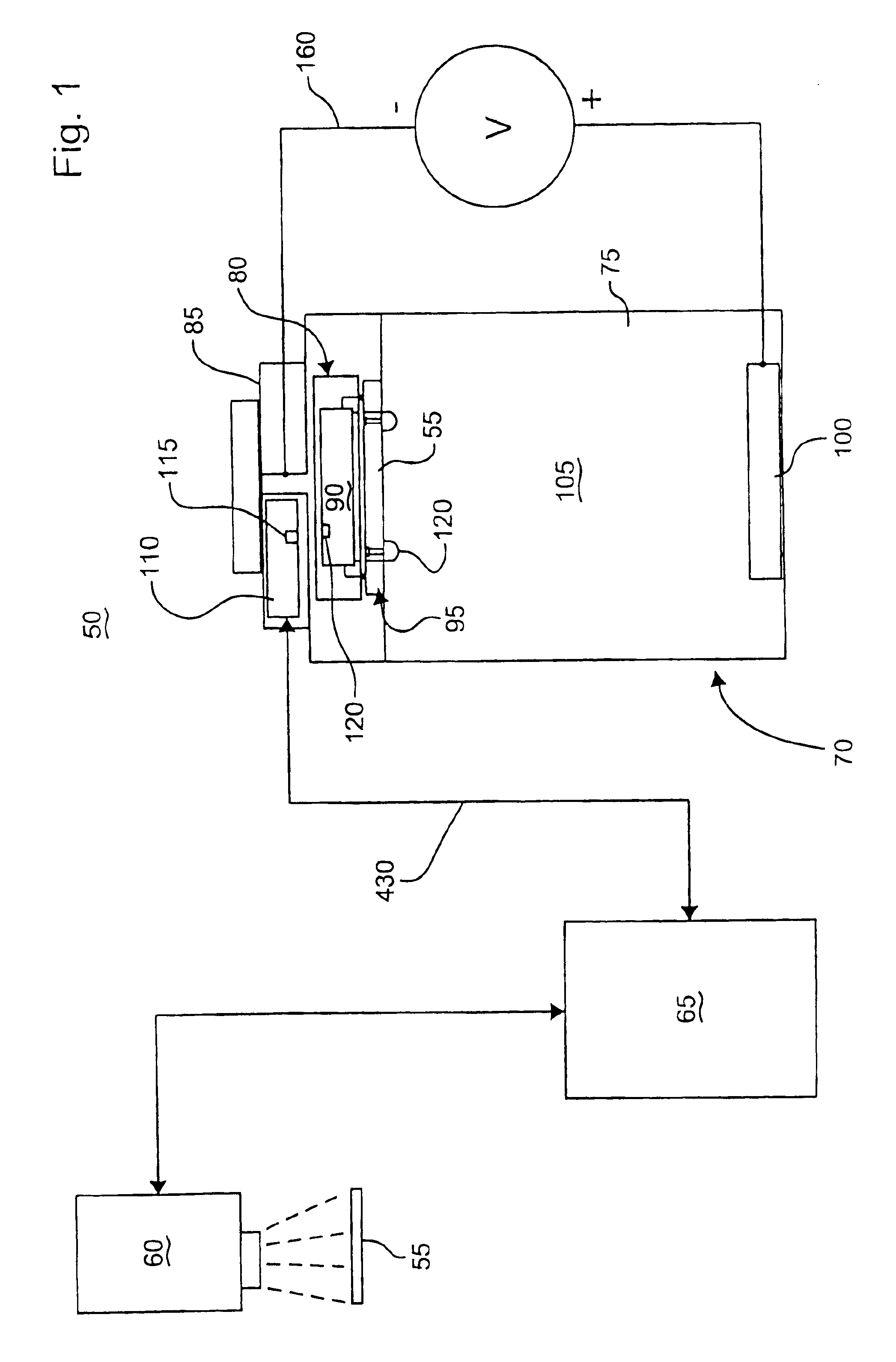
FIG. 1 is a schematic block diagram of a plating system, shown generally at 50, for electroplating a metallization layer, such as a patterned copper metallization layer, on, for example, a semiconductor wafer 55. The illustrated system generally comprises a vision system 60 that communicates with a main electroplating control system 65. The vision system 60 is used to identify the particular product being formed on the semiconductor wafer 55 before it is placed into an electroplating apparatus 70. With the information provided by the vision system 60, the main electroplating control system 65 may set the various parameters that are to be used in the electroplating apparatus 70 to electroplate the metallization layer on the wafer 55.

In the illustrated system, the electroplating apparatus 70 is generally comprised of an electroplating chamber 75, a rotor assembly 80, and a stator assembly 85. The rotor assembly 80 supports the semiconductor wafer 55, a current control system 90, and a...


PUM

PropertyMeasurementUnit
voltageaaaaaaaaaa
currentaaaaaaaaaa
electroplating currentaaaaaaaaaa

Abstract

A cathode current control system employing a current thief for use in electroplating a wafer is set forth. The current thief comprises a plurality of conductive segments disposed to substantially surround a peripheral region of the wafer. A first plurality of resistance devices are used, each associated with a respective one of the plurality of conductive segments. The resistance devices are used to regulate current through the respective conductive finger during electroplating of the wafer. Various constructions are used for the current thief and further conductive elements, such as fingers, may also be employed in the system. As with the conductive segments, current through the fingers may also be individually controlled. In accordance with one embodiment of the overall system, selection of the resistance of each respective resistance devices is automatically controlled in accordance with predetermined programming.

Description

STATEMENT REGARDING FEDERALLY SPONSORED RESEARCH OR DEVELOPMENTNot ApplicableBACKGROUND OF THE INVENTIONMost inorganic and some organic chemical compounds, when in a molten state or when dissolved in water or other liquids, become ionized; that is, their molecules become dissociated into positively and negatively charged components, which have the property of conducting an electric current. If a pair of electrodes is placed in a solution of an electrolyte, or an ionizable compound, and a source of direct current is connected between them, the positive ions in the solution move toward the negative electrode and the negative ions toward the positive. On reaching the electrodes, the ions may gain or lose electrons and be transformed into neutral atoms or molecules, the nature of the electrode reactions depending on the potential difference, or voltage, applied.The action of a current on an electrolyte can be understood from a simple example. If the salt copper sulfate is dissolved in w...

Claims


Application Information

Patent Timeline
Patent Type & Authority Patents(United States)
IPC IPC(8): G06F9/38G06F9/30
CPCC25D17/007C25D17/00C25D17/001
Inventor BERNER, ROBERT W.FATULA, JR., JOSEPH J.HITZFELD, ROBERTCONTRERAS, RICHARDCHIU, ANDREW
Owner SEMITOOL INC
Why Eureka
Try Eureka