
Alignment system and methods for lithographic systems using at least two wavelengths

a technology of alignment system and lithographic system, which is applied in the direction of lasers, printers, instruments, etc., can solve the problems of affecting the accuracy of the on-axis alignment method, the difficulty of improving the alignment system sufficiently to achieve the required precision and accuracy, and the decrease in the size of components, etc., to achieve the effect of improving the alignment accuracy and/or robustness

Active Publication Date: 2005-01-18
ASML NETHERLANDS BV
View PDF54 Cites 54 Cited by
  • Summary
  • Abstract
  • Description
  • Claims
  • Application Information

AI Technical Summary

Benefits of technology

It is thus an object of the present invention to provide an alignment system for a lithographic apparatus that has improved alignment accuracy and / or robustness.

Problems solved by technology

However, with the continued decrease in the size of components on ICs and the increase in complexity, on-axis alignment systems have proven to be difficult to improve sufficiently to achieve the required precision and accuracy.
However, this polishing process affects the accuracy of the on-axis alignment method.
However, the CMP process renders the substrate grating mark asymmetrical so that this alignment method is no longer reliable.
Since the signal strength of monochromatic light reflected from such a phase grating varies periodically with the depth of the grooves, the processing can render grating marks undetectable in some cases or provide only a weak signal in other cases.
This leads to a decrease in the robustness of the alignment system in that there are cases when an expected alignment detection cannot be made due to a loss of signal strength.
This can also lead to a decrease in alignment precision if a weak signal is used to determine the position of the alignment mark.
However, the use of light sources in such systems that are in the visible region of the spectrum, e.g., a red and a green laser, results in situations where the signals at both wavelengths are weak, thus leading to problems with robustness and precision of detection of the alignment marks on the substrate.

Method used


Image

  • Alignment system and methods for lithographic systems using at least two wavelengths
  • Alignment system and methods for lithographic systems using at least two wavelengths
  • Alignment system and methods for lithographic systems using at least two wavelengths

Examples


Embodiment Construction

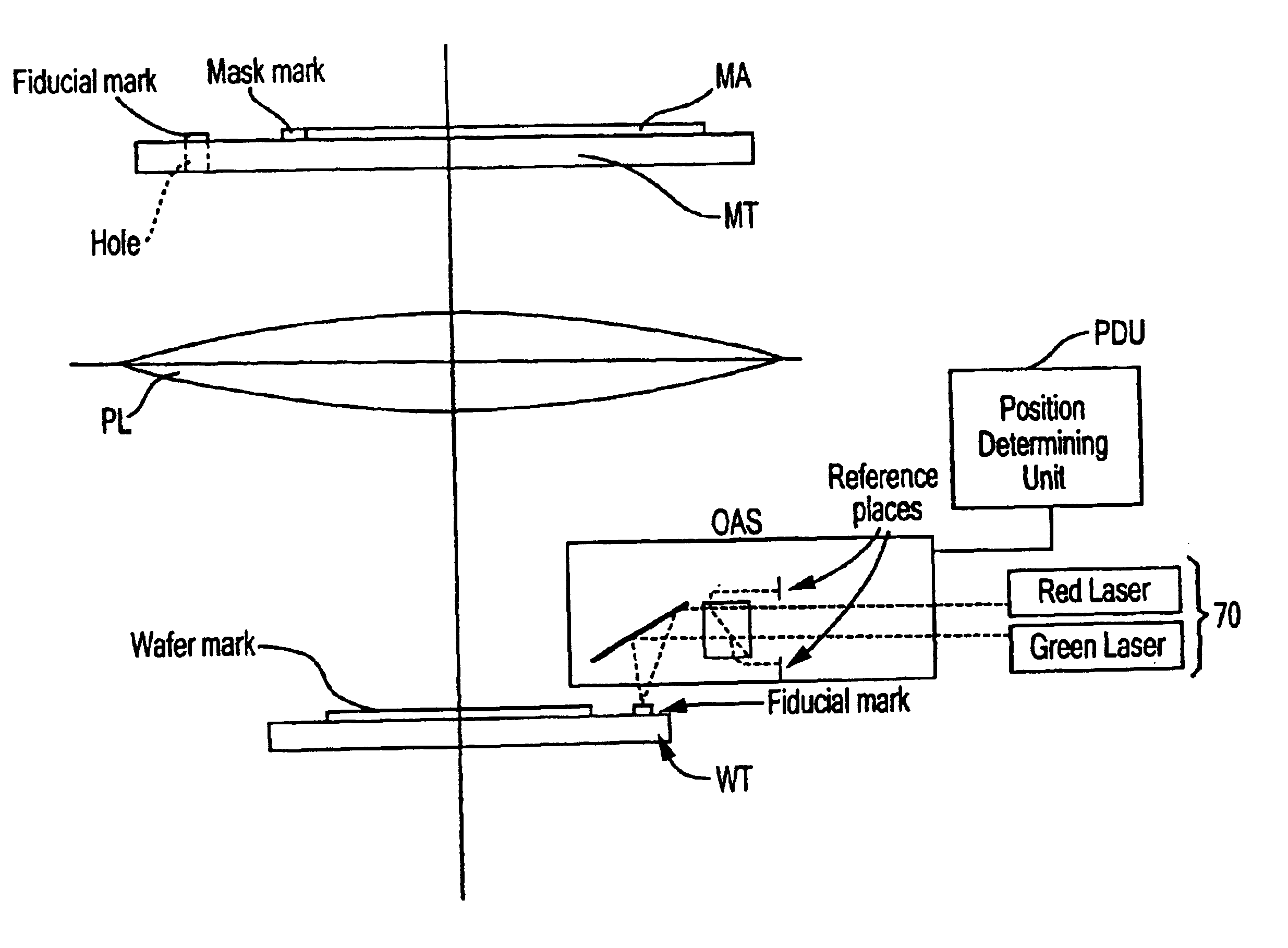
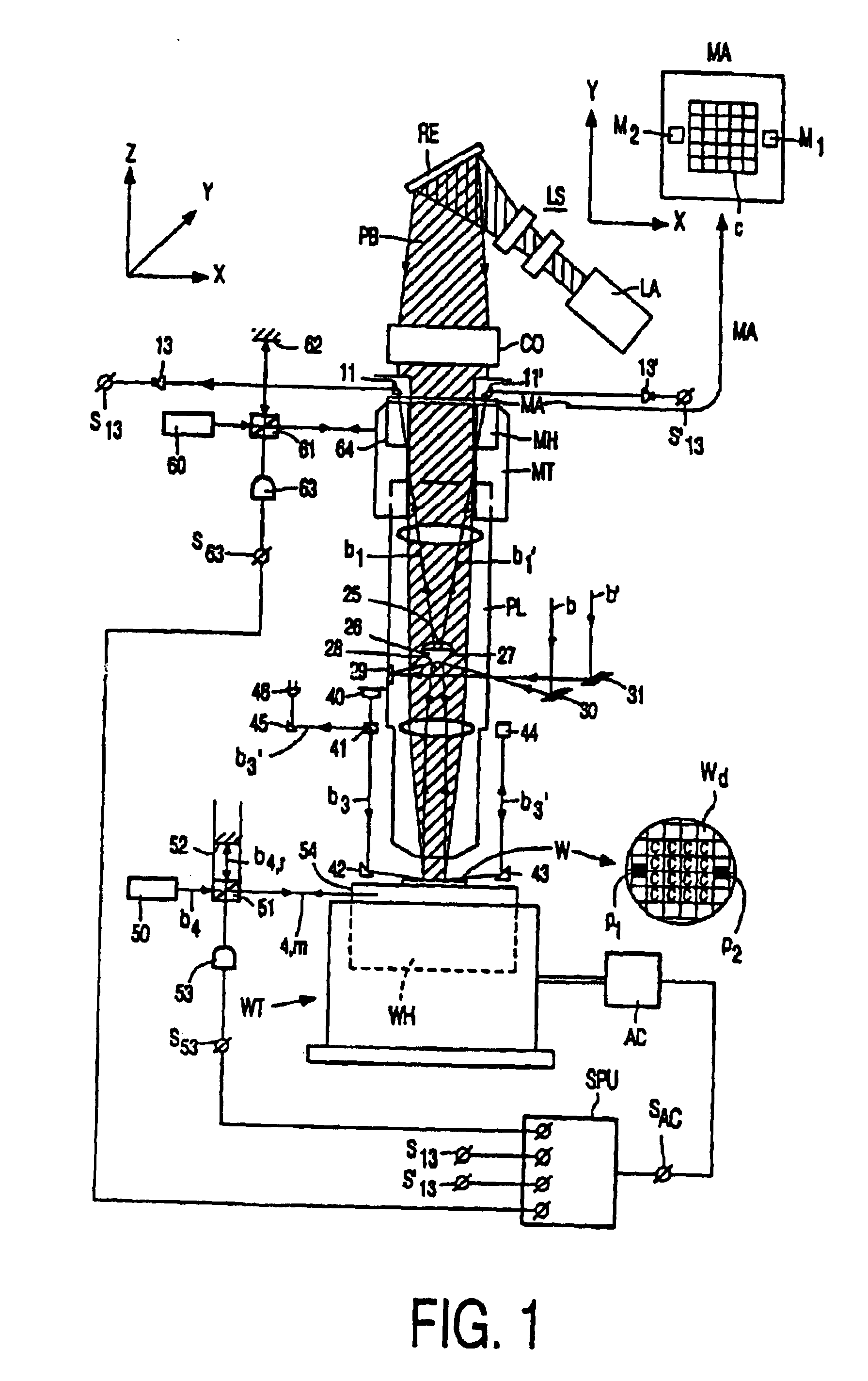
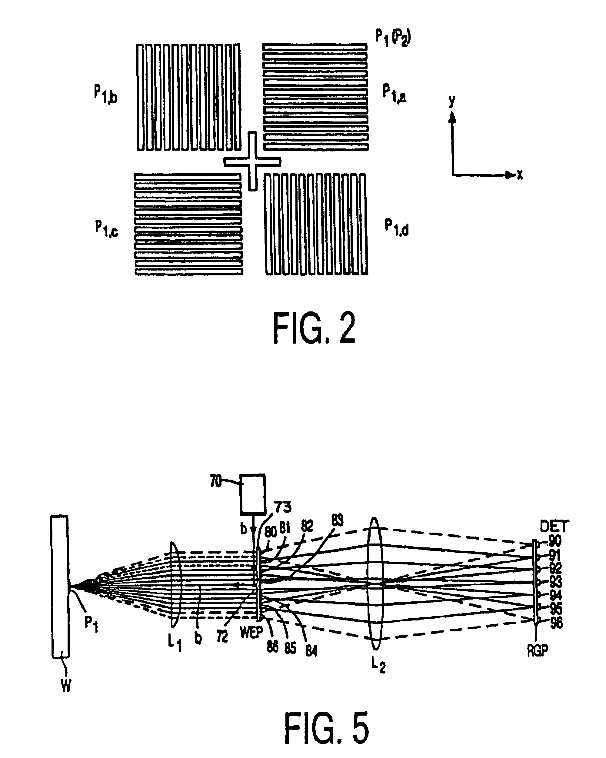
Methods and devices according to this invention will now be described with reference to particular embodiments by way of example. The broad concepts of this invention are not limited to only these specifically described embodiments. The invention will be described with reference to an alignment system for a lihography system that includes both an on-axis (also referred to as “axial”) and an off-axis (“off-axial”) alignment system that can be used in combination to obtain the ultimate alignment of a mask with respect to a substrate (“workpiece”). The axial alignment system may have a separate source of radiation to illuminate alignment marks, such as in through-the-lens (TTL) or through-the-reticle (TIR) systems, or it may employ the same radiation as the exposure radiation. The following example will describe a TTL system in combination with an off-axial system (OAS) as an embodiment of this invention. Furthermore, the invention envisions application to lihography systems that have ...


PUM


Abstract

An alignment system for a lithographic apparatus has a source of alignment radiation that has a first wavelength and a second wavelength; a detection system that has a first wavelength channel arranged to receive alignment radiation from an alignment mark at the first wavelength and a second wavelength channel arranged to receive alignment radiation from the alignment mark at the second wavelength; and a position determining unit in communication with the detection system. The position determining unit processes information from the first and second wavelength channels in combination to determine a position of the alignment mark based on information from the first wavelength channel, information from the second wavelength channel or combined information from the first and second wavelength channels according to a relative strength of the alignment radiation detected at the first wavelength to alignment radiation detected at the second wavelength. A lithographic apparatus includes the above alignment system. Methods of alignment and manufacturing devices use the above alignment system and lithographic apparatus, respectively.

Description

BACKGROUND OF THE INVENTION1. Field of InventionThis invention relates to an alignment system for a lithographic apparatus, and a lithographic apparatus having such an alignment system, and more particularly to an alignment system that can detect the position of an alignment mark using at least two separate wavelength signals.2. Discussion of Related ArtLithographic apparatuses are essential components for the manufacture of integrated circuits and / or other micro-devices. With the aid of such an apparatus, different mask patterns are successively imaged at a precisely aligned position onto a substrate such as a semiconductor wafer or an LCD panel. The substrate may undergo physical and chemical changes between the successive images that have been aligned with each other. The substrate is removed from the apparatus after it has been exposed with the image of a at least one mask pattern, and, after it has undergone the desired process steps, the substrate is placed back in order to ex...

Claims


Application Information

Patent Timeline
IPC IPC(8): G03F9/00G01B11/00G01B11/02G01B21/00G02B5/18G03F7/00G03F7/20G03F9/02H01L21/027H01L21/3205H01L21/68H01L23/52H01S3/00
CPCG03F9/7046G03F9/7049G03F9/7092G03F9/7084G03F9/7088G03F9/7076G03F9/7065
Inventor NAVARRO Y KOREN, RAMONSIMONS, HUBERTUS JOHANNES GERTRUDUSJEUNINK, ANDRE BERNARDUS
Owner ASML NETHERLANDS BV
Learn More