
Method for detecting engine knock

a technology of engine knock and detection method, which is applied in the direction of machines/engines, electrical control, instruments, etc., can solve the problems of engine knock, engine knock, and engine knock, and achieve the effect of reducing the power generation of internal combustion engines

Inactive Publication Date: 2005-01-18
WOODWARD GOVERNOR CO
View PDF14 Cites 37 Cited by
  • Summary
  • Abstract
  • Description
  • Claims
  • Application Information

AI Technical Summary

Benefits of technology

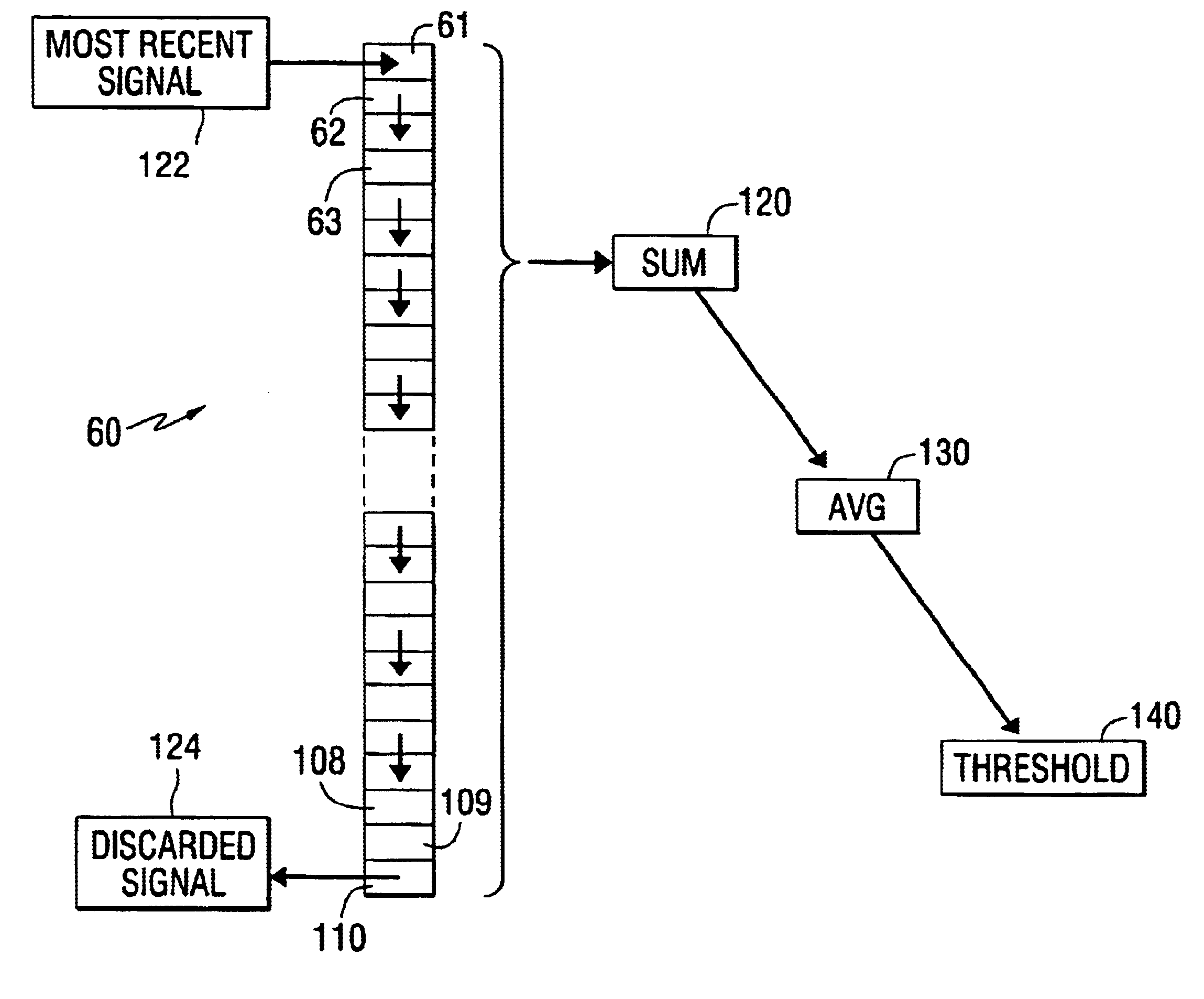
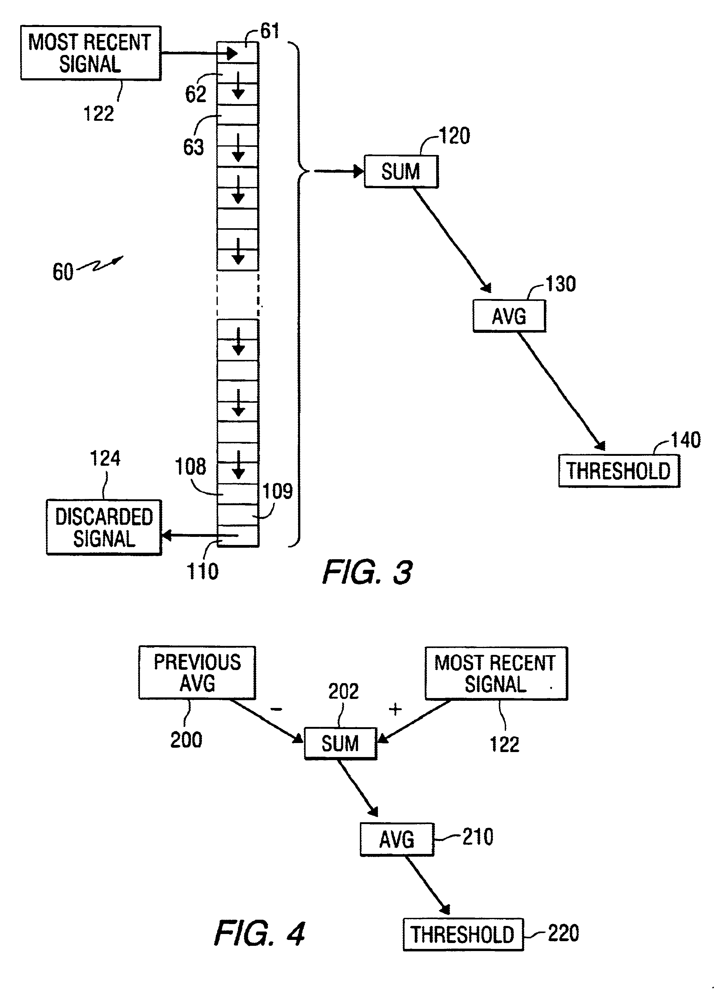
The present invention is described herein as comprising the determinations of a sum SN and a pseudo average AN according to the equations and procedures shown above. However, it should be understood that the method steps can be reduced to simplified mathematical equivalent steps in certain embodiments to achieve equivalent results. As an example, an initial pseudo average AN can be set to zero or some other value and then altered, after each receipt of a new value, by simply adding the difference between the previous pseudo average AN and the newly received value. In this simplified adaptation of the present invention, that difference could advantageously be modified by also multiplying it by a preselected factor which is preferably less than one. As an example of this technique, a previously determined pseudo average AN of 100 which is followed by a subsequent value of 120 would be modified by adding the difference (i.e. 20) between the previous pseudo average (i.e. 100) and the new value (i.e. 120) multiplied by a preselected decimal value (e.g. 0.03). This would result in a magnitude of 0.6 (i.e. 20 multiplied by 0.03) being added to the value of 100 to result in a new pseudo average AN of 100.6 which would then be used in subsequent calculations. It should be understood that the procedure described immediately above in this paragraph is equivalent to the procedure described in terms of equations 1 and 2 above and in the

Problems solved by technology

Improper combustion, which is commonly referred to as knock, is a well known limitation on internal combustion engine power generation.
When an additional flame front is initiated at the cylinder walls due to the increasing temperature and pressure resulting from the spark initiated flame front, engine knock will occur.
When these two flame fronts collide with each other within the combustion chamber, cylinder pressure spikes and resonates causing piston and valve pitting, and crankshaft and rod bearing degradation.
However, the use of a running sum or average has certain inherent disadvantages.
In addition, the manipulation of the data in the buffer takes time to execute.

Method used


Image

  • Method for detecting engine knock
  • Method for detecting engine knock
  • Method for detecting engine knock

Examples


Embodiment Construction

Throughout the description of the preferred embodiment of the present invention, like components will be identified by like reference numerals.

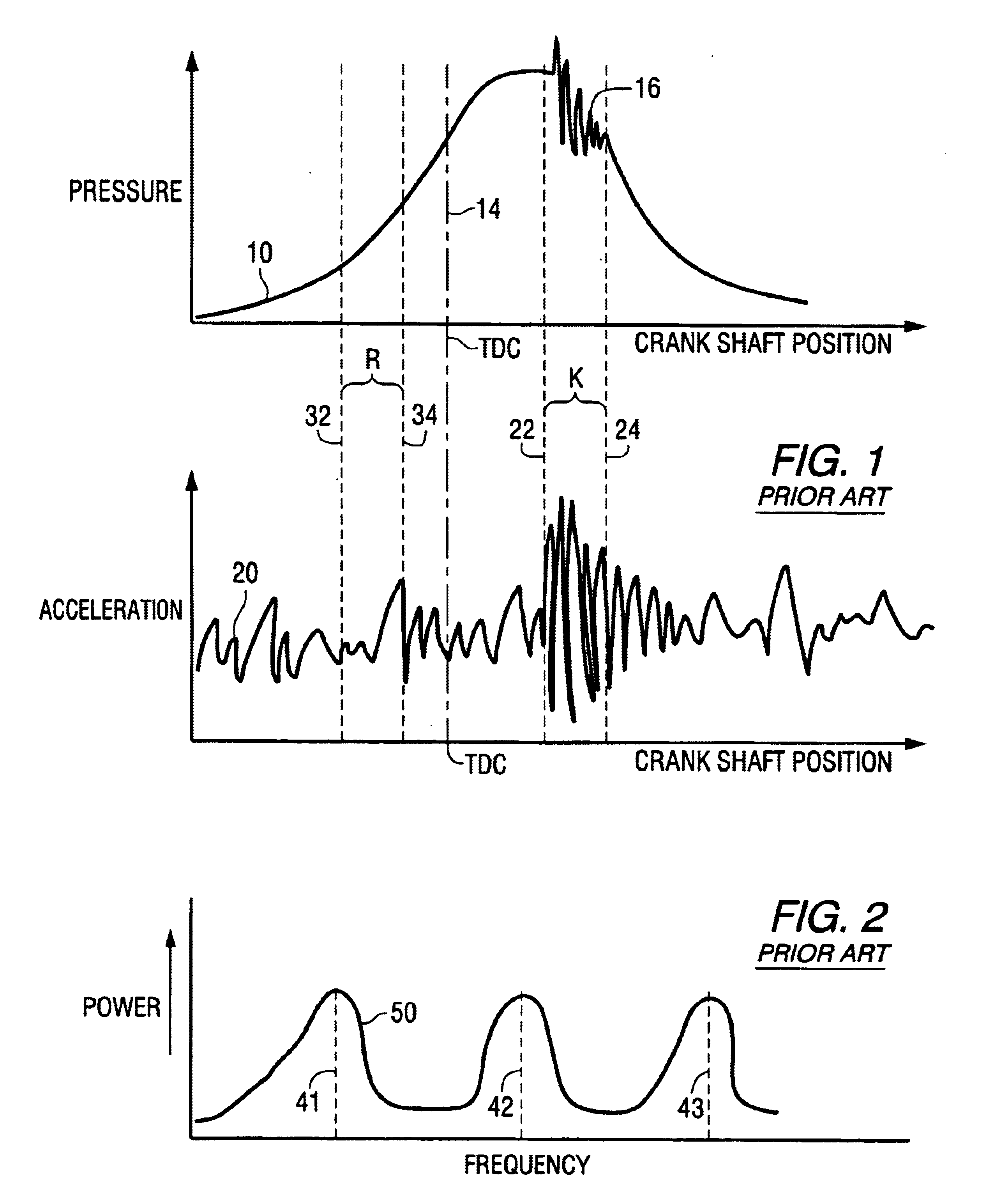
As is well known to those skilled in the art, engine knock can be detected either with pressure sensors or accelerometers. FIG. 1 shows two graphical representations of alternate ways of detecting engine knock. In the upper graph, curve 10 shows the pressure magnitudes within a cylinder as a function of crankshaft position. For purposes of reference, dashed line 14 represents the top dead center position of the crankshaft. The perturbations in the pressure curve, identified by reference numeral 16, represent fluctuations in pressure within the combustion chamber that result from the phenomenon known as knock or detonation.

The lower curve 20 in FIG. 1 represents and amplitude measurement provided by an accelerometer attached to an engine. The accelerometer measures the amplitude of vibration of the engine and provides a signal representing tha...


PUM

PropertyMeasurementUnit
thresholdaaaaaaaaaa
threshold valueaaaaaaaaaa
temperatureaaaaaaaaaa

Abstract

A method for processing knock-related data reduces the memory locations required for the method and also simplify the processing steps needed to determine a sum, average, and threshold value relating to magnitudes of knock ratios. Inputs from either pressure sensor or accelerometers are filtered and then used to form a ratio between a knock portion of a curve and a reference portion. Sequential magnitudes of the knock ratio are received and analyzed in a manner that reduces required memory locations and improves processing speed.

Description

BACKGROUND OF THE INVENTION1. Field of the InventionThe present invention is generally related to a method for detecting the occurrence of engine knock events and, more particularly, to a strategy which achieves the advantages of a moving average technique without the inherent disadvantages of requiring significant memory for storing data and time for data manipulations and calculations.2. Description of the Prior ArtImproper combustion, which is commonly referred to as knock, is a well known limitation on internal combustion engine power generation. To achieve maximum engine power, it is necessary to appreciate the disadvantages of engine knock and provide an efficient method for detecting it.When an additional flame front is initiated at the cylinder walls due to the increasing temperature and pressure resulting from the spark initiated flame front, engine knock will occur. When these two flame fronts collide with each other within the combustion chamber, cylinder pressure spikes ...

Claims


Application Information

Patent Timeline
Patent Type & Authority Patents(United States)
IPC IPC(8): F02P5/152F02D35/02F02D37/02F02D41/24G01L23/22
CPCF02D35/027F02D37/02F02P5/152G01L23/225Y02T10/46F02D41/2403Y02T10/40
Inventor CROSS, TRAVIS A.TARTT, JASONKIRCHHOFF, THOMAS S.
Owner WOODWARD GOVERNOR CO
Learn More