
Method and apparatus for inter-cylinder lubrication transfer in a multi-cylinder internal combustion engine

a multi-cylinder, internal combustion engine technology, applied in the direction of auxilary lubrication, lubrication elements, pressure lubrication, etc., can solve the problems of increased pollutants exhausted from the engine, excess lubricant drawn, and consumption of crankcase fluid, so as to improve lubrication, reduce output pollutants, and facilitate oil movement

Inactive Publication Date: 2005-01-25
BRP US
View PDF13 Cites 9 Cited by
  • Summary
  • Abstract
  • Description
  • Claims
  • Application Information

AI Technical Summary

Benefits of technology

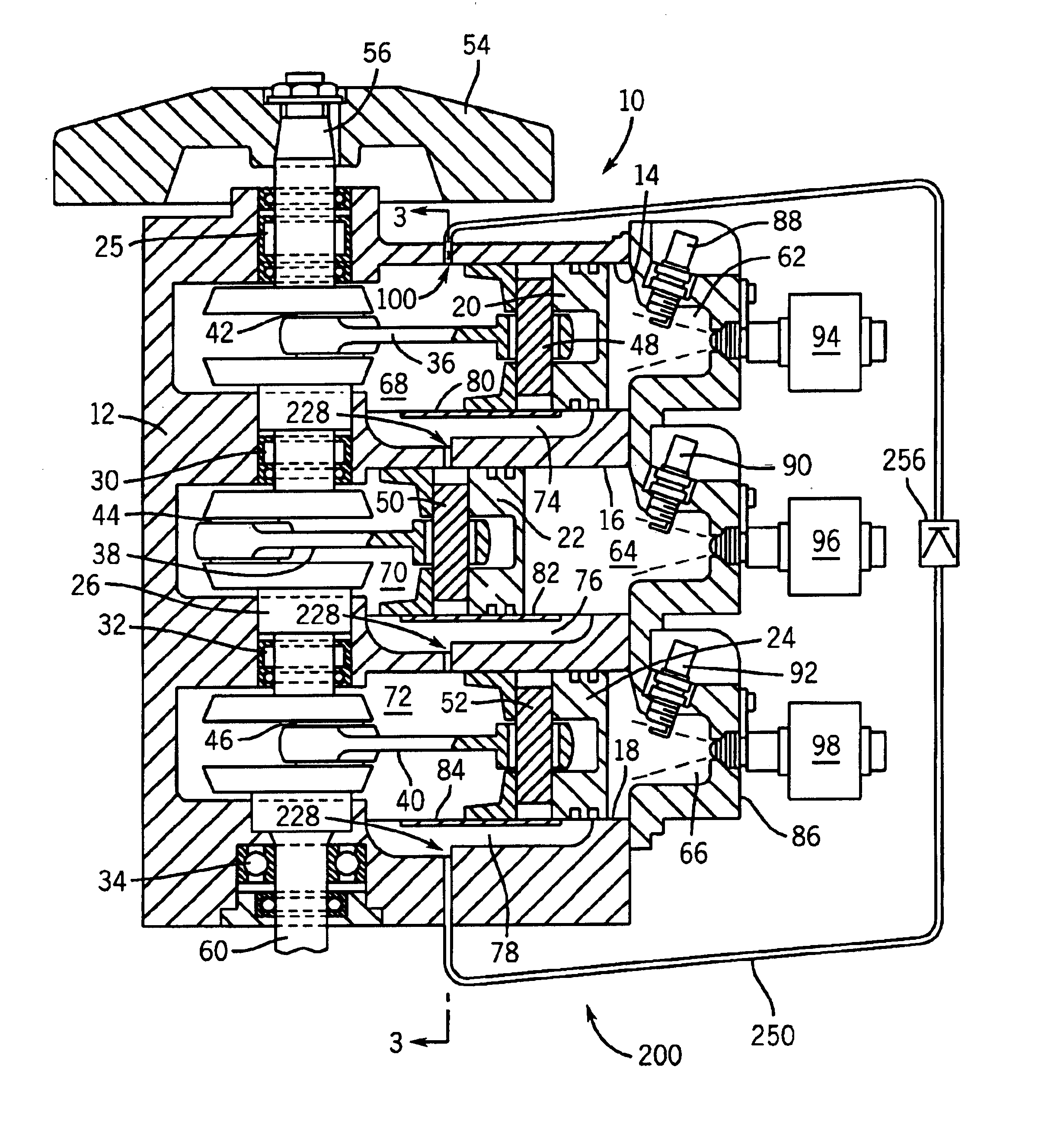
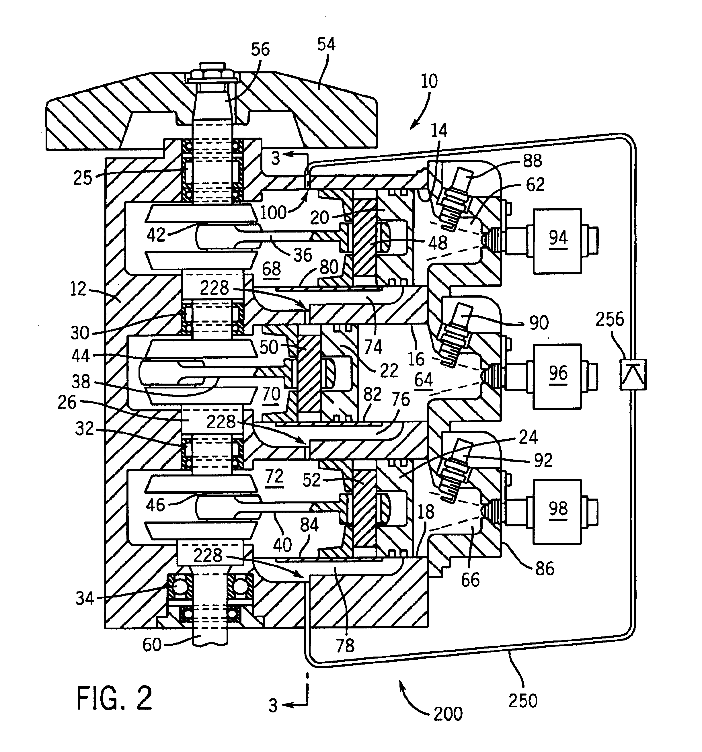
The present invention is directed to a lubrication system for an internal combustion engine overcoming the aforementioned drawbacks. The invention provides a system which improves lubrication, oil utilization, and reduces output pollutants of a multi-cylinder two-stroke crankcase-scavenged internal combustion engine. The system gathers excess oil that has completed its lubrication task in a given cylinder, and relocates this excess oil in an adjacent cylinder that is downstream of the upstream cylinder. This process in continued from one cylinder to the next until the lowest most cylinder is reached, as which point, oil is returned to the upper-most cylinder. The oil passages are strategically placed so that the excess oil is accumulated at a lowest point in each cylinder before it reaches the combustion chamber, and the inlet passages to each cylinder are strategically placed such that the piston, and more specifically the skirt of the piston, acts as a valve opening and closing this oil inlet port. In this manner, the invention takes advantage of pressure differentials between cylinders to encourage oil movement by opening the port only when the pressure is higher in the supplying crankcase as compared to the pressure in the receiving crankcase. Accordingly, each cylinder of the engine receives improved lubrication and the oil is utilized in a much more efficient manner, and less oil is passed into the combustion chamber and exhausted at pollutants. This results in improved engine durability, lower oil consumption, and lower operating costs, as well in assisting in meeting lower emissions standards.

Problems solved by technology

In such prior art engines, this excess lubricant is drawn into the combustion chamber with the crankcase fluid and is consumed in the combustion process.
This leads to increased pollutants exhausted from the engine and inefficient use of oil.

Method used


Image

  • Method and apparatus for inter-cylinder lubrication transfer in a multi-cylinder internal combustion engine
  • Method and apparatus for inter-cylinder lubrication transfer in a multi-cylinder internal combustion engine
  • Method and apparatus for inter-cylinder lubrication transfer in a multi-cylinder internal combustion engine

Examples


Embodiment Construction

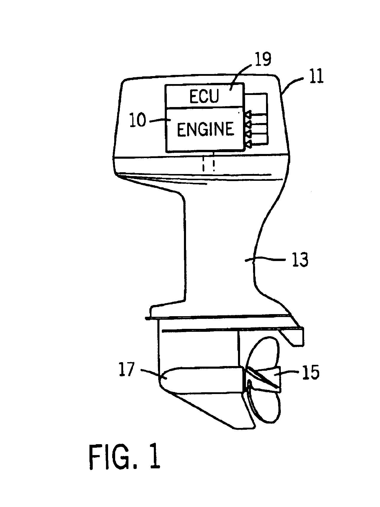
The present invention is applicable to two-stroke engines that can be arranged in which gravitational forces can have detrimental effects on emission levels and lubrication. Applications for such engines can include outboard marine engines, personal watercraft engines, snowmobiles, lawn and garden equipment, etc. One such engine 10, illustrated in FIG. 1, comprises an outboard two-stroke internal combustion engine. The engine is housed in a powerhead 11 and supported on a mid-section 13 configured for mounting on the transom of a boat (not shown) in a known conventional manner. An output shaft (not shown) of the engine 10 is coupled to drive a propeller 15 extending rearwardly of a lower gearcase 17 via the mid-section 13. The engine 10 is controlled by an electronic control unit (ECU) 19. While the present invention is shown in FIG. 1 as being incorporated into an outboard motor, the present invention is also applicable with many other applications, including inboard or stern drive...


PUM


Abstract

The present invention is directed to a lubrication system for a multi-cylinder internal combustion engine. An inter-cylinder lubricant communications system is provided to circulate lubricant from an upper-most cylinder to each successive cylinder downstream. This system includes an inlet that extends through an opening in the wall of a downstream cylinder. An outlet situated upstream relative to the inlet is also provided and includes an accumulation region to collect lubricant as it flows with the charging air from the crankcase chamber to the combustion chamber of an engine cylinder. A fluid passage is configured to fluidly interconnect the inlet to the outlet to pass lubricant from the upstream cylinder to the downstream cylinder. A passage is provided from the most downstream cylinder to the most upstream cylinder thereby allowing for re-circulation of the lubricant. The system takes advantage of a pressure differential between any two successive cylinders to draw the excess oil from one cylinder to the next.

Description

BACKGROUND OF THE INVENTIONThe present invention is related generally to internal combustion engines, and, more particularly, to an inter-cylinder lubrication system for a two-cycle internal combustion engine.In certain known internal combustion engines, a cylinder block can be arranged with two banks of vertically-stacked cylinders. In a six-cylinder engine, for example, each cylinder bank has three cylinders. Each cylinder includes a sleeve and a piston which moves relative to the sleeve between top dead center and bottom dead center positions. It will be appreciated that the foregoing terminology of top dead center and bottom dead center is used for the sake of traditional usage and is not meant to describe the piston / cylinder geometry in engines having vertically-stacked cylinders since the reciprocating motion of the piston occurs along a generally horizontal axis as opposed to the more traditionally oriented vertical axis. As indicated from the traditional “top dead center” an...

Claims


Application Information

Patent Timeline
Patent Type & Authority Patents(United States)
IPC IPC(8): F01M1/00F01M1/04F02B61/04F02B61/00F01M1/08
CPCF01M1/04F02B61/045F01M2001/083
Inventor HAMAN, DAVID F.
Owner BRP US
Learn More