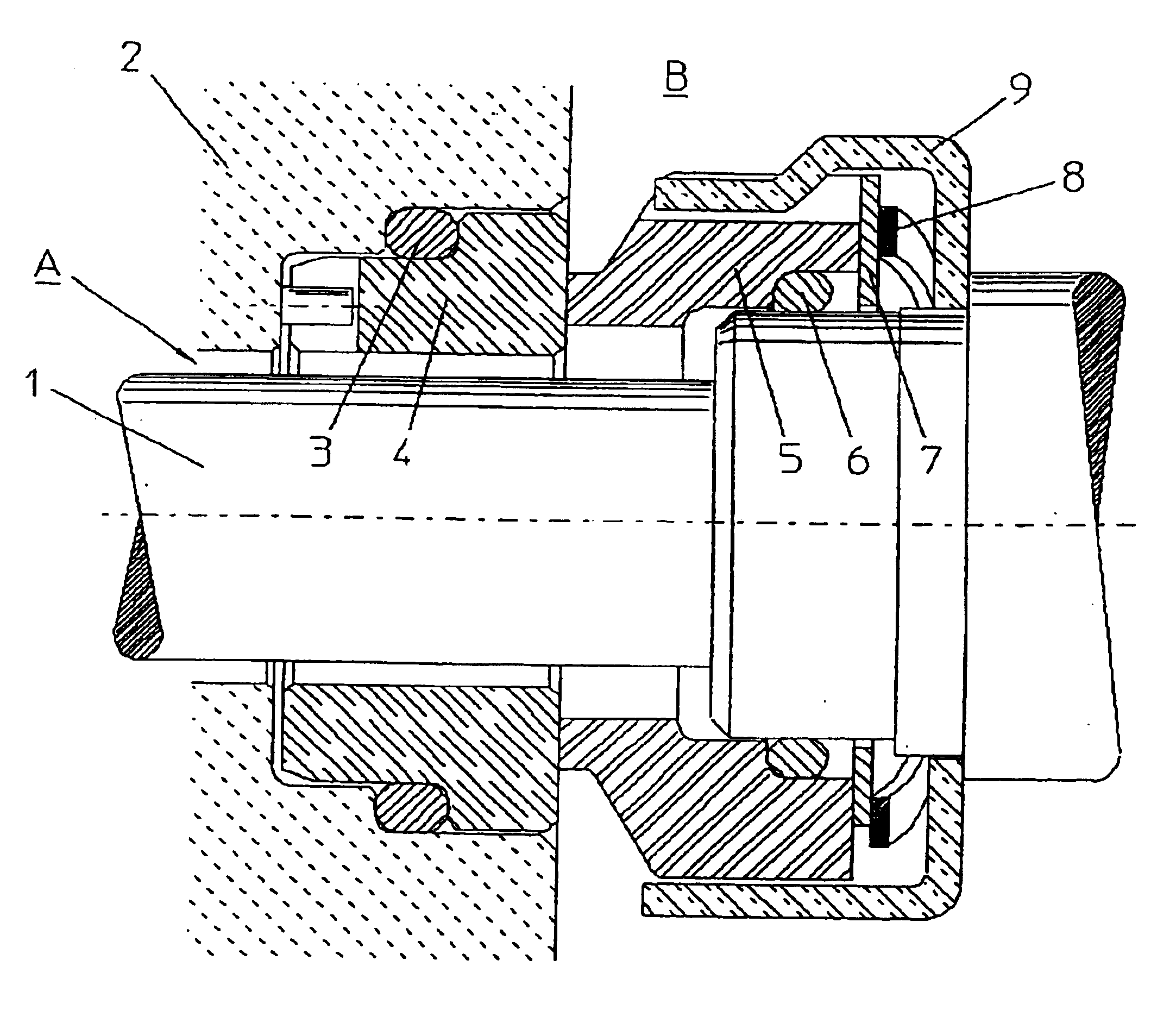
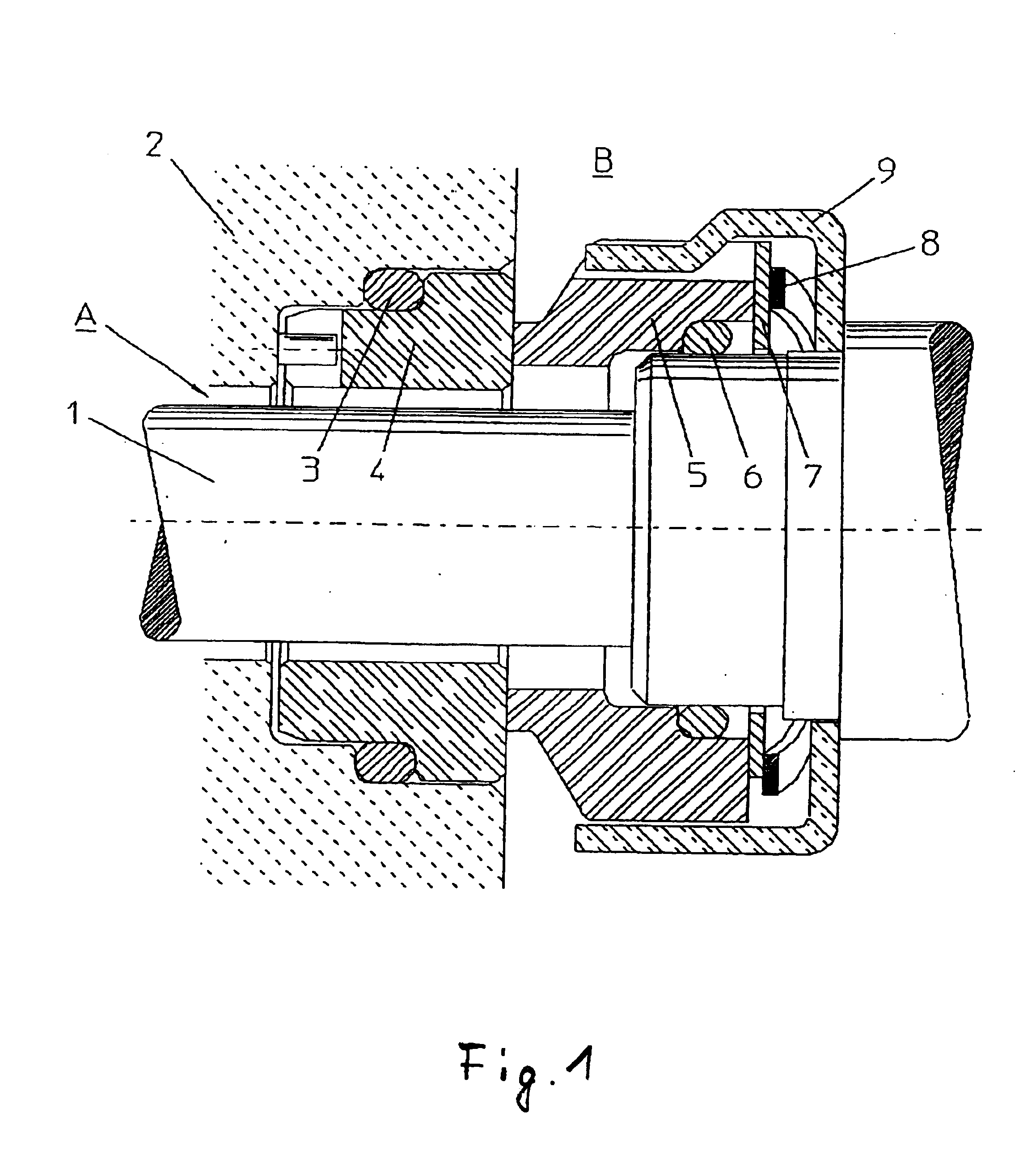
Rotating mechanical seal
- Summary
- Abstract
- Description
- Claims
- Application Information
AI Technical Summary
Benefits of technology
Problems solved by technology
Method used
Image

Examples
Embodiment Construction
The carbon and silicon carbide composite material exhibits a structure created through partial conversion of the surface layer of the carbon substrate into a silicon carbide material. The silicon carbide material is preferably formed by way of reactive or atmospheric sintering. The silicon carbide material preferably exhibits a silicon carbide content of at least 85% or higher. In this way, sufficient surface hardness and modulus of elasticity are guaranteed.
The carbon and silicon carbide composite material is obtained through partial conversion of the surface layer of the carbon substrate into a silicon carbide material and exhibits a higher modulus of elasticity than common carbon slip-promoting materials so that it is minimally susceptible to deformation, even at high pressure, and nonetheless incorporates a self-lubricating, carbon-containing component whereby problems such as erosion, surface roughness and the like are minimized even under poor lubrication conditions. A combina...
PUM
| Property | Measurement | Unit |
|---|---|---|
| Length | aaaaa | aaaaa |
| Length | aaaaa | aaaaa |
| Length | aaaaa | aaaaa |
Abstract
Description
Claims
Application Information