

Process for production of pattern-forming body
a technology of pattern-forming body and process, which is applied in the direction of diffusion transfer process, photosensitive materials, instruments, etc., can solve the problems of deterioration of photoresist, control of laser strength, and need for waste liquid treatmen
- Summary
- Abstract
- Description
- Claims
- Application Information
AI Technical Summary
Benefits of technology
Problems solved by technology
Method used
Image

Examples
example 1
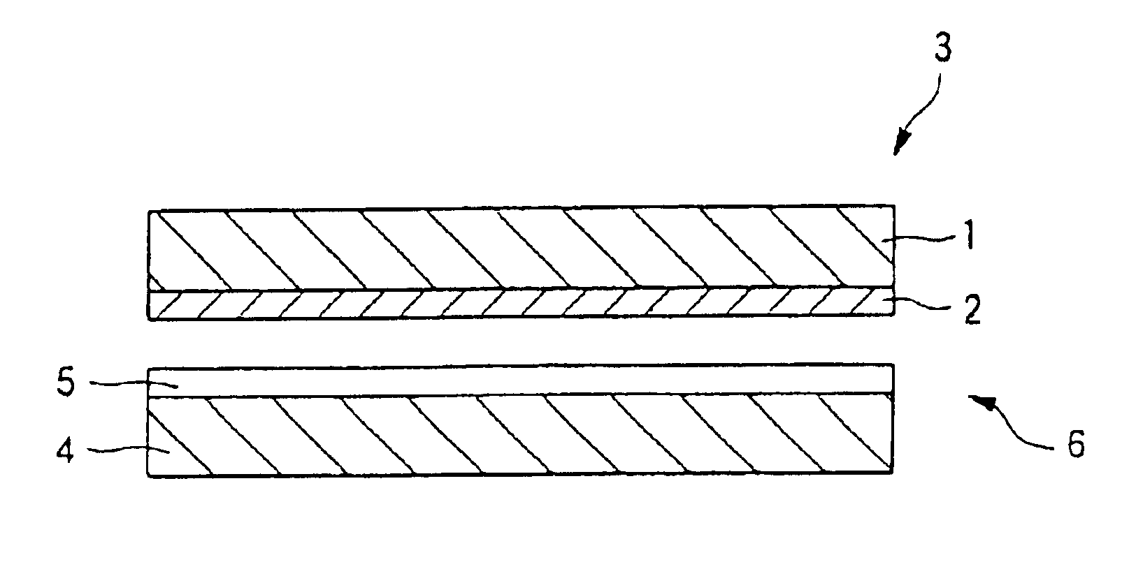
1. Formation of a Photocatalyst-containing Layer-side Substrate
30 g of isopropyl alcohol, 0.4 g of MF-160E (trademark, manufactured by Tochem Products) using fluoroalkylsilane as its major component, 3 g of trimethoxymethylsilane (manufactured by Toshiba Silicone, trademark: TSL8113) and 20 g of ST-K01 (trademark, manufactured by Ishihara Sangyo Inc.) which was a titanium dioxide / water dispersion as a photocatalyst were mixed and stirred at 100° C. for 20 minutes. The resulting mixture was diluted with isopropyl alcohol to bring the total volume to three times the original, thereby preparing a composition for a photocatalyst-containing layer.
The above composition was applied to a transparent substrate made of soda glass by a spin coater and was subjected to drying treatment performed at 150° C. for 30 minutes to form a transparent photocatalyst-containing layer (thickness: 0.2 μm), thereby forming a photocatalyst-containing layer-side substrate.
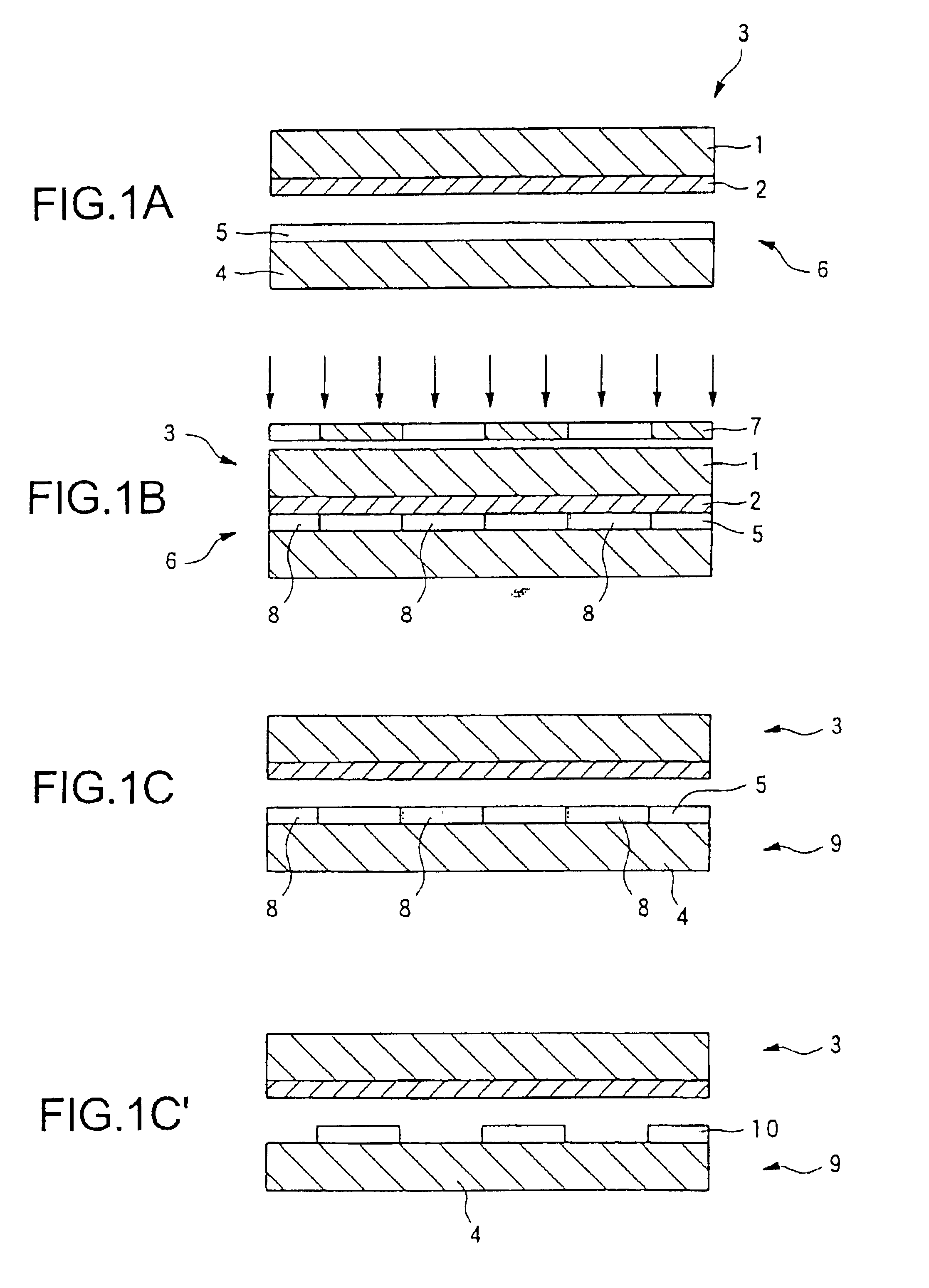
2. Formation of a Pattern-forming Body...
example 2
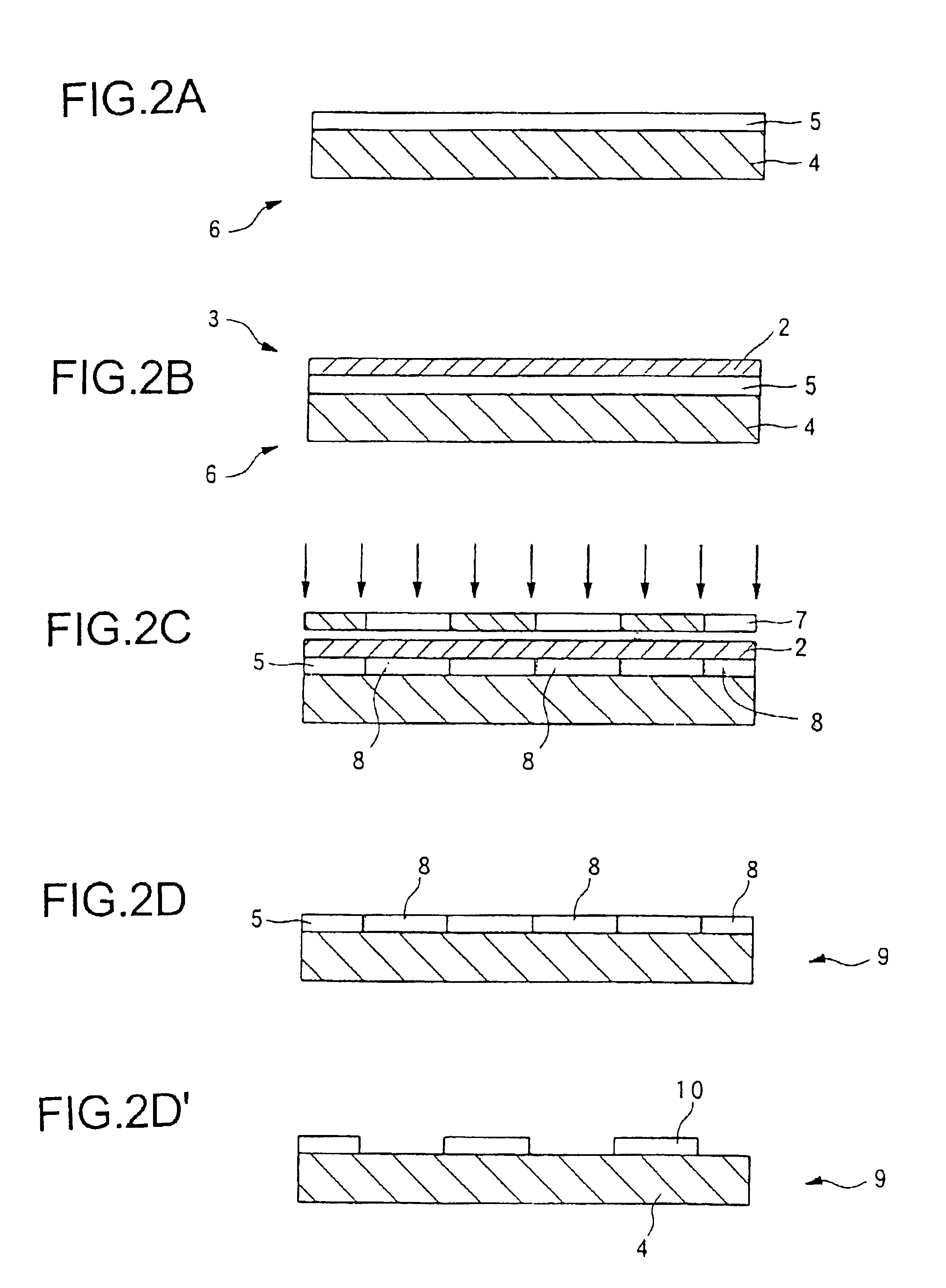
1. Preparation of a Photocatalyst-containing Layer-side Substrate and a Pattern-forming Body Substrate
A pattern-forming body substrate was prepared in the same manner as in Example 1. Thereafter, the same composition for a photocatalyst-containing layer as that used in Example 1 was applied to the wettability-changeable layer of the pattern-forming body substrate by a spin coater and heated at 150° C. for 30 minutes to form a photocatalyst-containing layer with a thickness of 0.2 μm, thereby preparing a photocatalyst-containing layer-side substrate.
2. Exposure
The photocatalyst-containing layer-side substrate was exposed to light from the side of the photocatalyst-containing layer in the same manner as in Example 1. Then, an adhesive tape (manufactured by Sumitomo 3M, trademark: Scotch Tape) was stuck to the photocatalyst-containing layer under pressure and then peeled off at a rate of 1 mm / sec. to peel off the photocatalyst-containing layer. The contact angle of the wettability-chan...
example 3
1. Formation of a Photocatalyst-containing Layer-side Substrate
15 g of ethanol, 15 g of isopropyl alcohol and 30 g of ST-K03 (trademark, manufactured by Ishihara Sangyo) which was a water dispersion of titanium dioxide as a photocatalyst were mixed and stirred at 100° C. for 20 minutes to prepare a composition for a photocatalyst-containing layer. This composition was applied to a transparent substrate made of soda lime glass by a dip coater and was subjected to heat treatment performed at 150° C. for 10 minutes to form a transparent photocatalyst-containing film (thickness: 0.2 μm), thereby forming a photocatalyst-containing layer-side substrate.
2. Formation of a Pattern-forming Body Substrate
2 wt % of a fluorine type nonionic surfactant ZONYL FSN (trademark, manufactured by Du Pont) was mixed in isopropanol to prepare a composition for a decomposition-removable layer. This composition for a decomposition-removable layer was applied to a transparent substrate made of soda lime glas...
PUM
| Property | Measurement | Unit |
|---|---|---|
| contact angle | aaaaa | aaaaa |
| contact angle | aaaaa | aaaaa |
| contact angle | aaaaa | aaaaa |
Abstract
Description
Claims
Application Information