
Minimal access lumbar diskectomy instrumentation and method
a technology for lumbar diskectomy and instrumentation, which is applied in the field of minimal access lumbar posterior surgery, can solve the problems of large incisions, difficult maintenance, and large stretching of structures, and achieve the effects of less incisions, less central docking, and excellent exposur
- Summary
- Abstract
- Description
- Claims
- Application Information
AI Technical Summary
Benefits of technology
Problems solved by technology
Method used
Image

Examples
Embodiment Construction
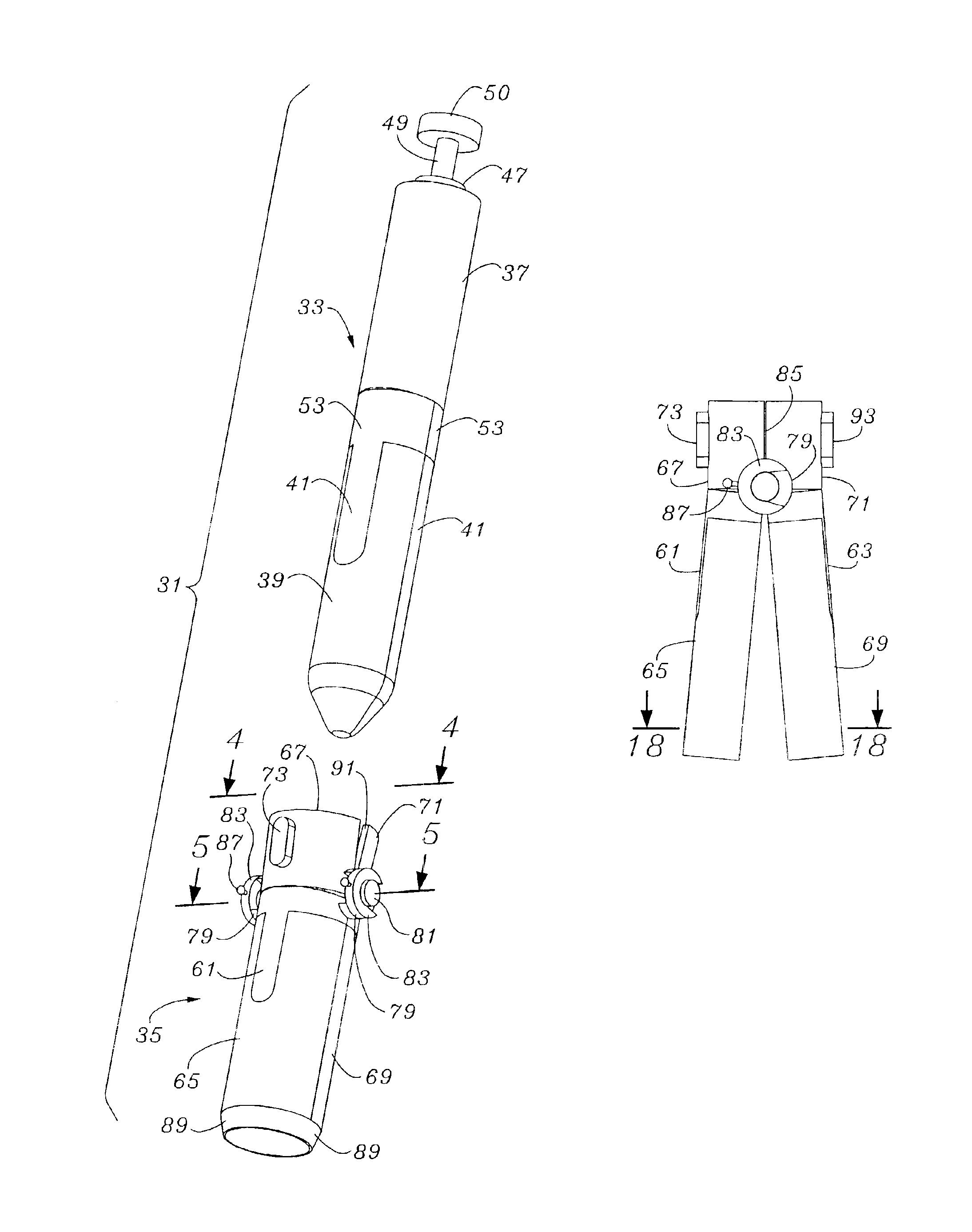
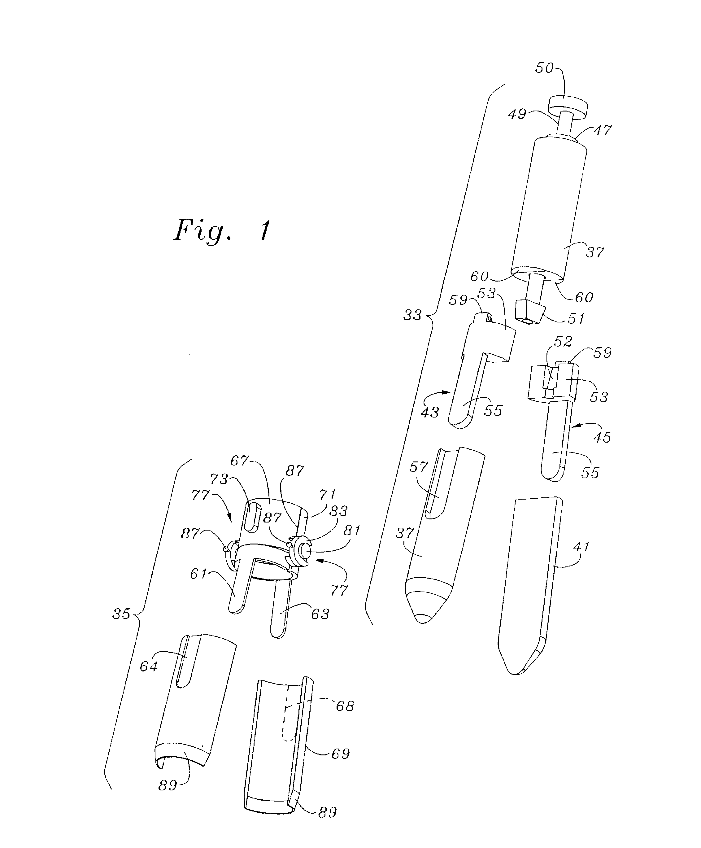
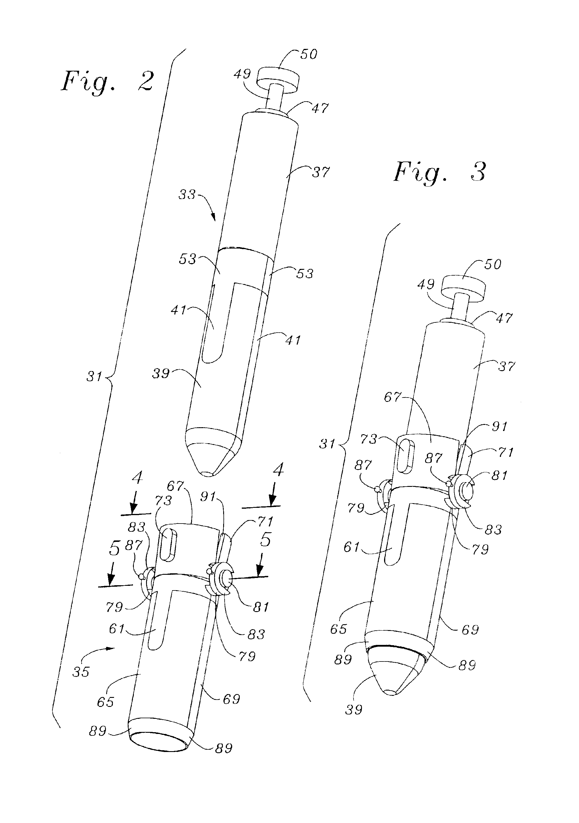
The description and operation of the minimal incision maximal access system will be best described with reference to FIG. 1 and identifying a general system 31. System 31 includes an obturator 33 and a working tube 35. The orientation of the obturator 33 is in a slightly displaced from a position of alignment with the working tube 35 for entry into working tube 35 and to provide the initial carefully controlled force for spreading the working tube 35, as will be shown.
Obturator includes an upper control housing 37 and a pair of spreading legs 39 and 41. The spreading legs 39 and 41 are seen as coming together to form a conical tip and thus have hemi conical end portions. The spreading legs 39 and 41 overfit attachment leg portions 43 and 45, respectively. At the top of the upper control housing 37 a boss 47 surrounds and supports the extension of a control shaft 49. A knurled thumb knob 50 sits atop the control shaft 49 to facilitate controlled turning of the control shaft 49 to con...
PUM
 Abstract
Description
Claims
Application Information