
Artillery firing mechanism

a firing mechanism and firing mechanism technology, applied in the direction of firing/trigger mechanism, breech mechanism, weapon, etc., can solve the problems of limiting the user's use, unable to achieve a high firing rate, and air trapped, so as to reduce the loading cycle time and increase the firing rate

Inactive Publication Date: 2005-02-08
SINGAPORE TECH KINETICS
View PDF9 Cites 15 Cited by
  • Summary
  • Abstract
  • Description
  • Claims
  • Application Information

AI Technical Summary

Benefits of technology

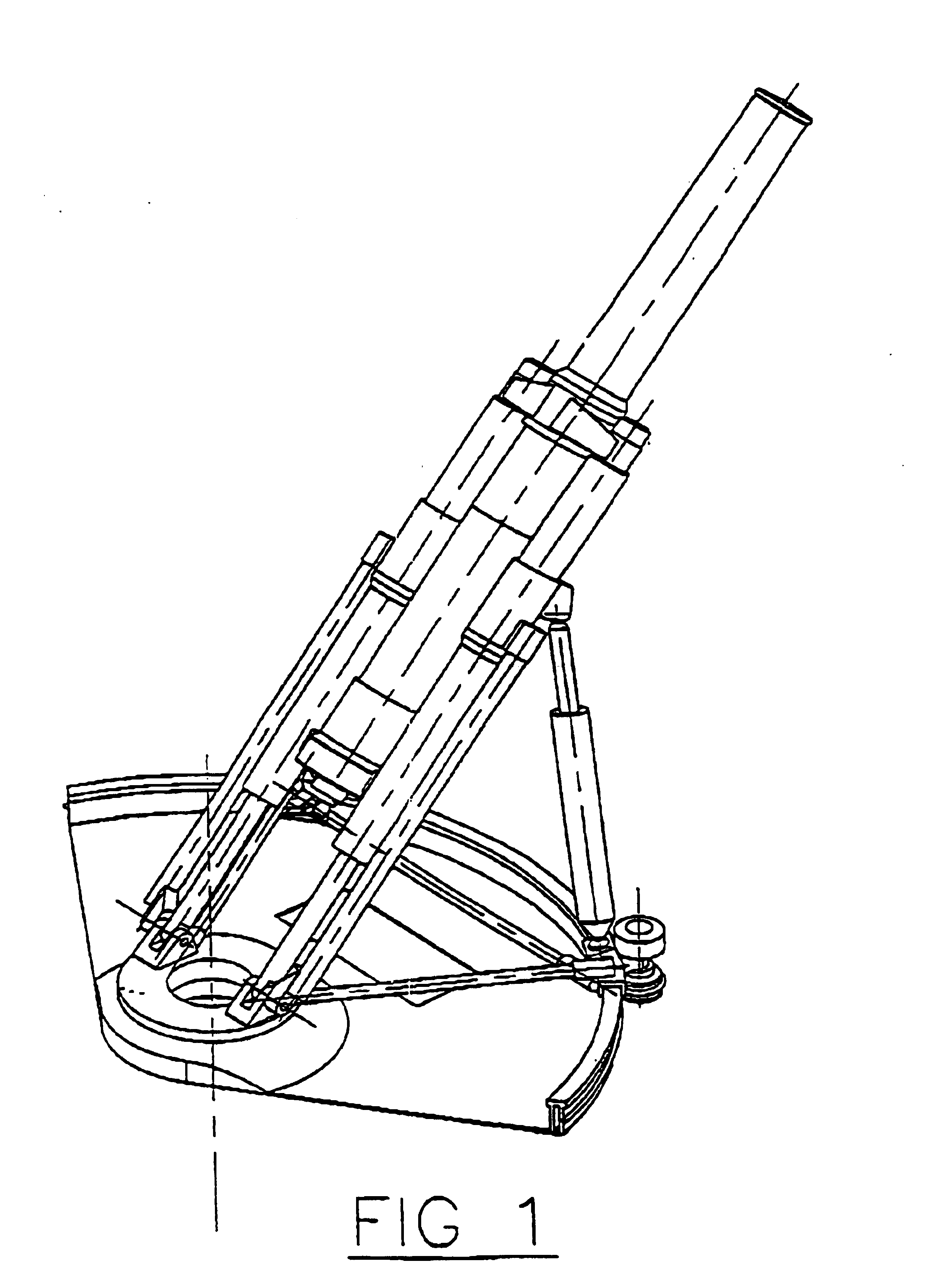
Three other current mortar systems that achieve slightly higher rates of firing as compared to conventional mortar systems are as follows:1. The Advanced Mortar System (see S / N 2 in Table A) which has twin barrels with an automatic breech loading system, has achieved a rate of firing of 14 rounds per minute. The performance compared to an increase in complexity using a breech loading operating mechanism is not only insignificant, but also doubles the weight of the whole system.2. The Multiple Mortar System (see S / N 3 in Table A) which has four barrels and uses an automatic muzzle loading system, has achieved a rate of firing of 12 rounds in 20 seconds but with extra preparation time. The weight and size of the whole system is substantially increased. The vehicle for carrying the system will be constrained by the weight and subsequently, will degrade its manoeuverability and mobility.3. The 82 mm AM 289 Vasilek Automatic Mortar (see S / N 4 in Table A) has an automatic breech loading system that operates like a machine gun. It has a linear magazine that holds four mortar bombs and the loading device is fitted behind the breech to allow rapid automatic firing. Only specially-designed bombs can be fitted in the magazine and although 120 rounds per minute can be fired, it still restricts the user from adopting the usage. Even though it is able to fire the standard bomb by muzzle loading, its performance will have no difference compared with other mortar systems.
The objective of the present invention is therefore to provide an artillery firing system, particularly suitable for mortars, that will effectively reduce the loading cycle time and increase the rate of fire.
A second objective of the present invention is to provide a self-sealing valve seat assembly which can maintain an operational condition in a dirty or dusty environment and high pressures and temperatures generated by the burning propellant to ensure the effectiveness of the valve used therein.
A third objective of the present invention is to provide a cooling system in order to reduce the propensity of the system from reaching Hot Barrel Temperature while maintaining an effective high rate of fire.
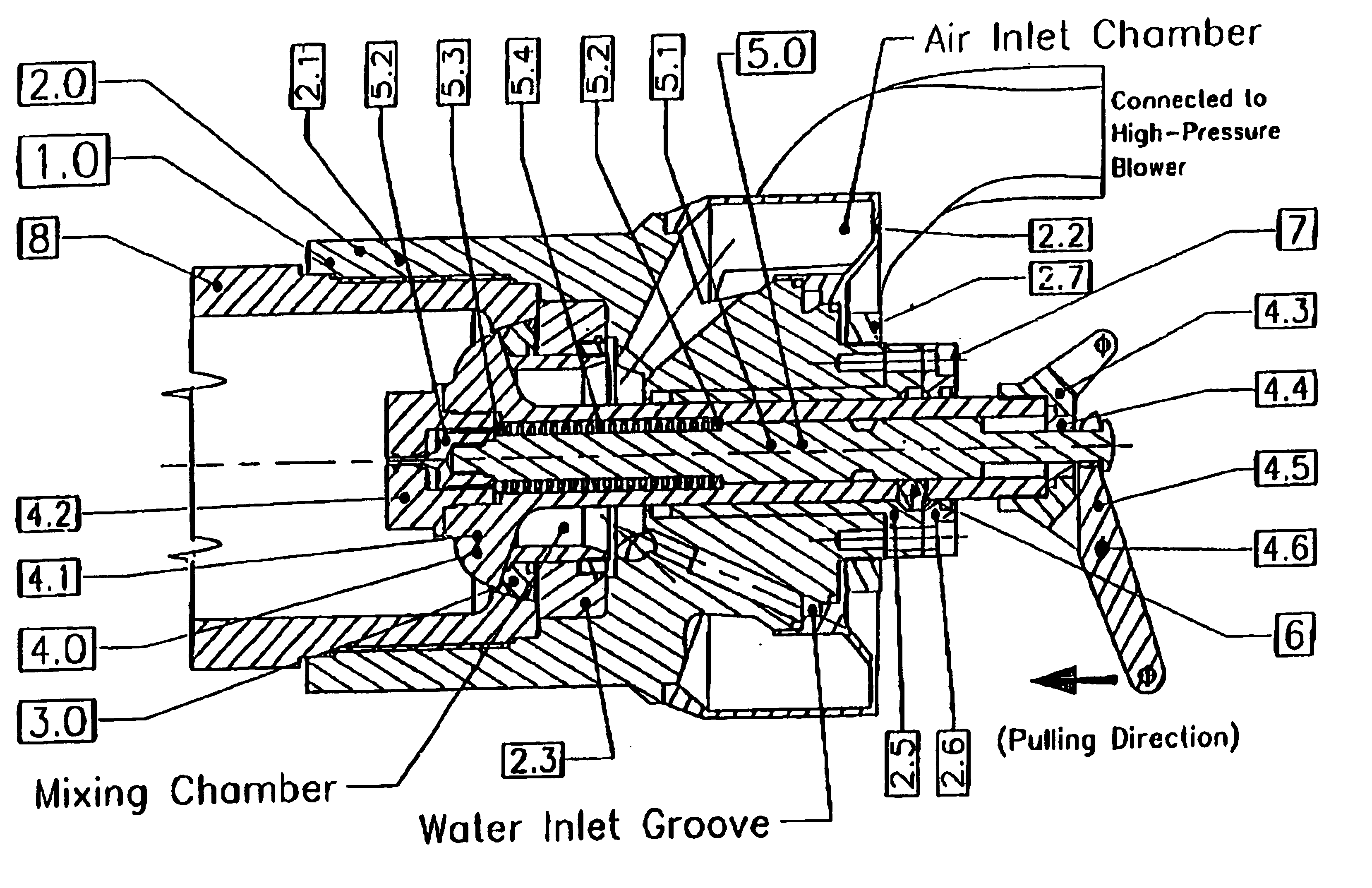
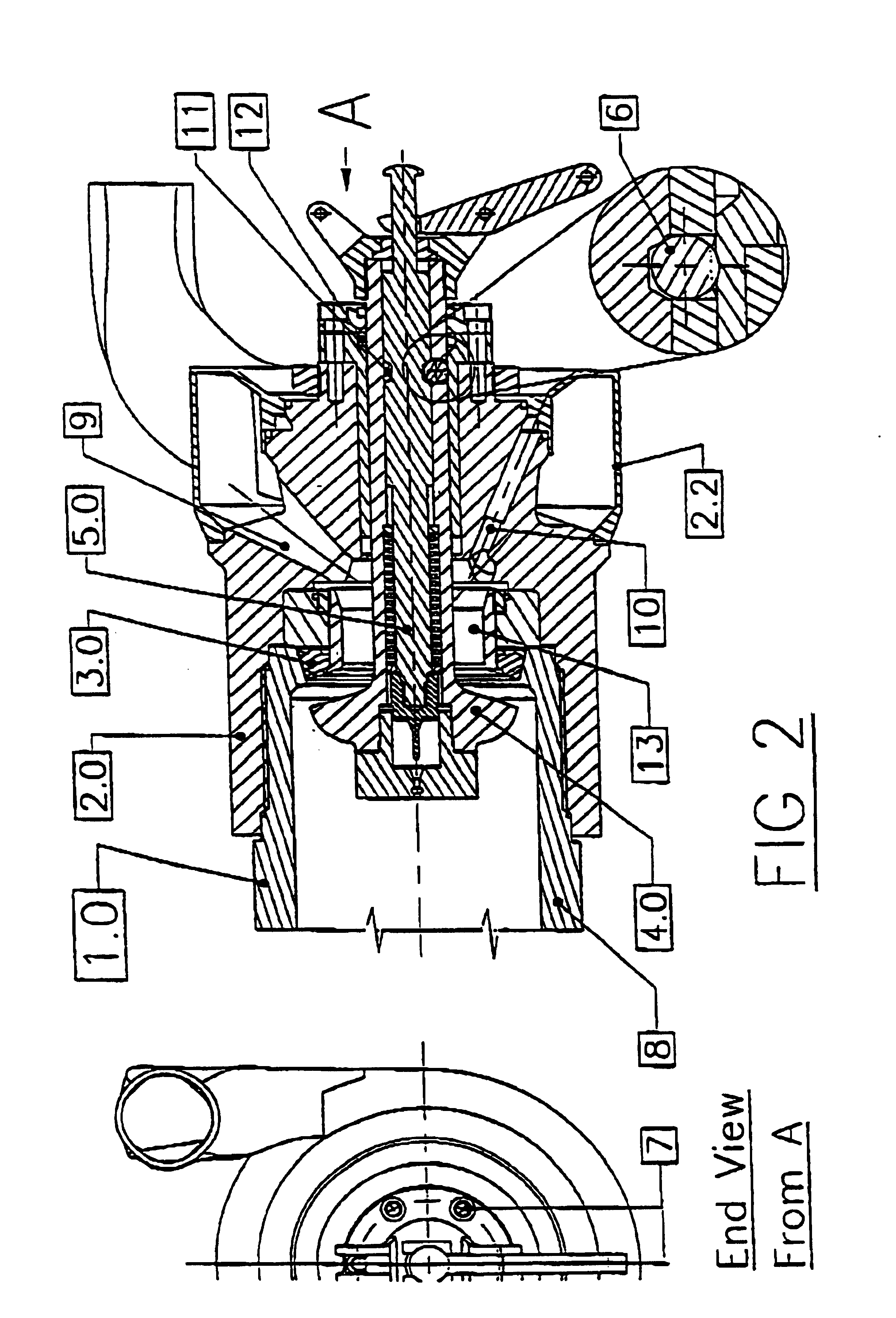
The present invention involves the incorporation of a valve assembly, preferably located towards the rear of the barrel. The valve assembly allows the air trapped inside the barrel to be expelled out of the barrel when the bomb is descending into the barrel to decrease the travelling time. It also allows the system to function in a dirty or dusty environment and under high temperatures and pressures. Additionally, a cooling system associated with the firing system provides air or moisture or any other suitable coolant to be introduced into the barrel to cool the barrel. Further, the valve assembly also permits a jet of air or any other suitable propellant gas to be forced into the barrel to dislodge or expel any misfired bomb lodged in the barrel.
The operation and structure of the preferred form of the invention should now be clear from the foregoing. Prior to loading of the projectile, the valve means is retained in the closed position by the retaining means, and the firing mechanism and the valve means are in the first relative position. The actuating means is then used to moved the valve means and the firing mechanism from the first relative position to the second relative position, against the force of the biasing means. This may be done by a human operator, or the process may be automated. When the valve means and the firing mechanism are in the first relative position, the retaining means now permits the valve body to move relative to the valve seat to open the valve means. While the valve means is in the open position, the retaining means will not permit any relative movement between the valve means and the firing mechanism. When the valve means reaches the open position, a projectile may be loaded into the bore through the muzzle of the barrel. As the projectile drops towards the firing mechanism, the air trapped in the bore can be expelled through the air vent in the breech assembly, with the assistance of the pump. The projectile eventually impacts the firing mechanism housing and this causes the valve body to move into contact with the valve seat and to close the valve. When the valve means is closed the retaining means permits the biasing means to force the valve means and the firing mechanism back into the first relative position. When this happens, the firing pin is moved through the aperture in the housing and into engagement with the projectile, thereby initiating firing of the projectile. The burning of propellant created by firing of the projectile builds up a pressure within the bore which presses the valve body against the valve seat and presses the valve seat against the breech assembly; in order to prevent leakage of hot gases through the air vent. The cycle is then repeated.

Problems solved by technology

However, such method is unsatisfactory if a high firing rate is required.
This occurs because when loading the mortar bomb from the muzzle into the mortar mechanism, air is trapped in between the mortar bomb and the barrel inside the mortar mechanism.
Thus, a high rate of firing cannot be achieved.
Only specially-designed bombs can be fitted in the magazine and although 120 rounds per minute can be fired, it still restricts the user from adopting the usage.
Another problem faced by conventional ways of firing is that, for each round of firing, the barrel temperature will increase approximately 2 to 4° C. With high rate of firing, the barrel temperature will increase tremendously to Hot Barrel Temperature within a short span of time.
However, currently, there are no cooling systems used in any mortar system.

Method used


Image

  • Artillery firing mechanism
  • Artillery firing mechanism
  • Artillery firing mechanism

Examples


example a

Heat Generated per Round FiredTemperature increase per round fired assumed to be 3° C.Weight of the Barrel assumed to be 80 kgTherefore,80 kg×3° C.×0.11=26,400 Calories

Amount of water required for c mpletely removing the heat generatedHeat of Vaporization of water at 1 atm:540 Calories / gramTherefore,26,400 Calories±540 Calories / gram≅49 gram (theoretical)

Convection Heat Transfer Coefficient5,000˜50,000 W / m2°C. (depending on the temperature difference)1 kW=239 Calories / second; Round-off to 240 Calories / secondTherefore1,200˜12,000 Calories / second

Water Flow EstimatedThe surface area of the Barrel Bore: φ0.12 m×π×2 m L=0.75 m2 If the heat Transfer Co-efficient of 12,000 Calories / second is achievable, then the optimal water flow rate should be: 12000⁢ ⁢Cal×0.75540⁢ ⁢Cal=16.67⁢ ⁢gm / sec

Cooling Cycle Time and its EfficiencyTime taken to load the mortar bomb and for it to travel inside the barrel 0.8 secTime taken to fire, recoil until the cooling valve opens 0.1 secTime taken to dry the barr...


PUM


Abstract

A firing apparatus (1.0) for a projectile-firing weapon of the type comprising a barrel (8) having a bore therein, the firing apparatus comprising a breech assembly (2.0) adapted to be secured to the barrel (8), a firing mechanism (5.0) adapted to initiate firing of the projectile from the bore, and a valve means (4.0)adapted to allow air within the bore, between the projectile and the firing mechanism (5.0), to be expelled from the bore during loading of the projectile through the bore.

Description

INTRODUCTIONThis invention relates to an artillery firing system featuring a mechanism which enables the firing system to attain a high a prolonged rate of fire, with a built-in cooling system in order to sustain the rate of fire. The invention is particularly suitable for use in a mortar system.PRIOR ART / PROBLEMSThe traditional and simplest way of firing a mortar is by way of a muzzle loading a mortar bomb. However, such method is unsatisfactory if a high firing rate is required. For insurance, a typical single barrel with automatic muzzle loading system. Turret Mortar Under Armour System see S / N 1 in Table A), can only achieve a rate of firing of about 12 rounds per minute. This occurs because when loading the mortar bomb from the muzzle into the mortar mechanism, air is trapped in between the mortar bomb and the barrel inside the mortar mechanism. As a result, the time taken for the mortar bomb to travel inside the barrel will be about 3 to 5 seconds and this will take up about 8...

Claims


Application Information

Patent Timeline
IPC IPC(8): F41A19/00F41A19/39F41A13/00F41A13/04F41F1/00F41F1/06
CPCF41A13/04F41F1/06F41A19/39
Inventor ANG, TEOH HWA
Owner SINGAPORE TECH KINETICS
Learn More