Small epicyclic magnetron with controlled radial sputtering profile

Inactive Publication Date: 2005-02-08
APPLIED MATERIALS INC
View PDF11 Cites 58 Cited by
  • Summary
  • Abstract
  • Description
  • Claims
  • Application Information

AI Technical Summary

Benefits of technology

A planetary magnetron may be used in a plasma sputter reactor for increased uniformity of sputter deposition, more complete target utilization, and increased plasma density. The magnetr

Problems solved by technology

Preferably, the engagement ratio should not be too close to an integral value, w

Method used


Image

  • Small epicyclic magnetron with controlled radial sputtering profile
  • Small epicyclic magnetron with controlled radial sputtering profile
  • Small epicyclic magnetron with controlled radial sputtering profile

Examples


Embodiment Construction

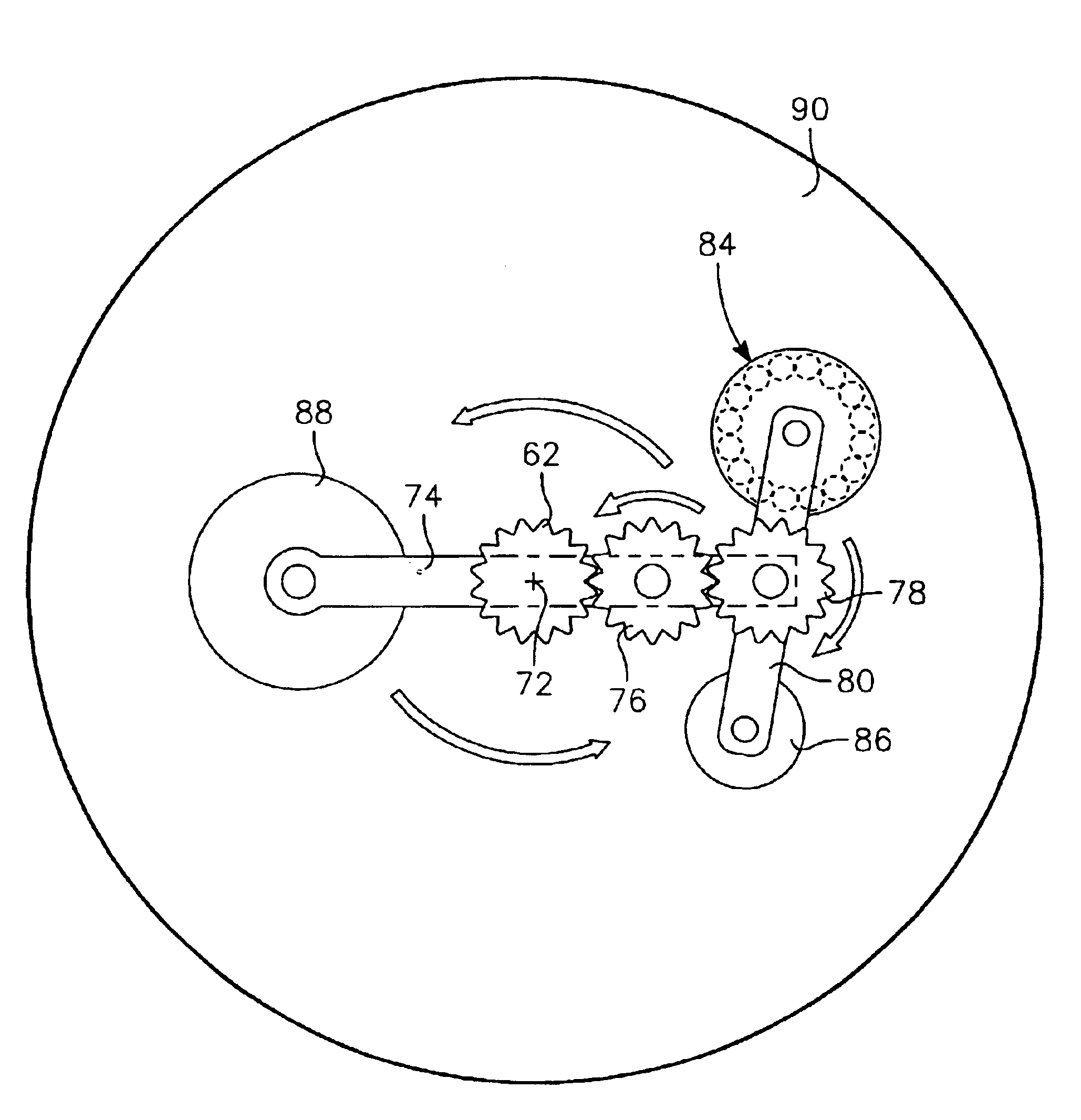
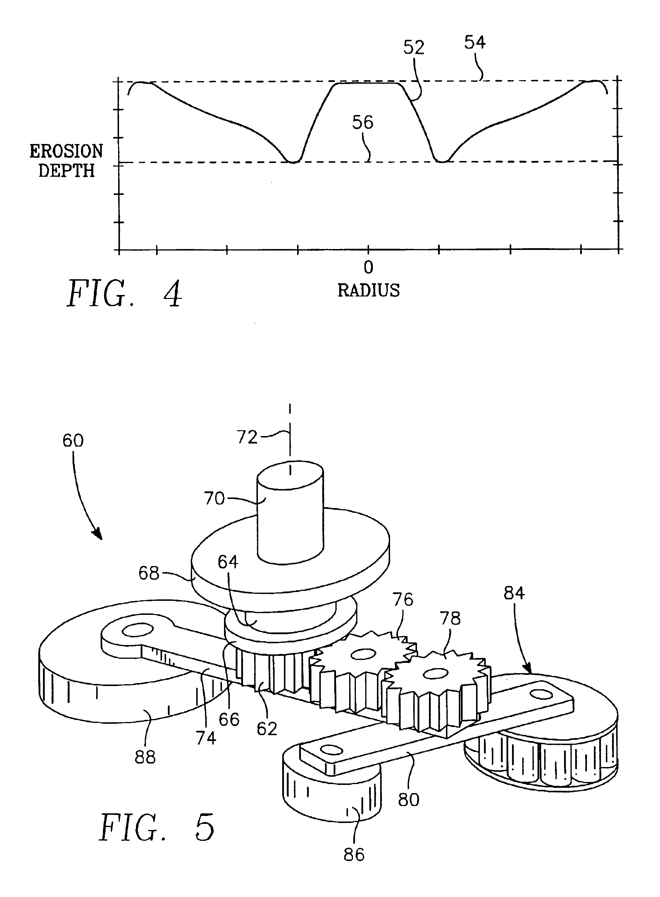
One principal embodiment of the invention relies upon a planetary mechanism, for instance, one using a single-stage planetary gear system, to allow a small circularly symmetric magnetron to fully cover the sputtering target. The planetary mechanism produces a planetary motion similar to that of a point on the surface of a planet orbiting the sun while it is simultaneously executing planetary rotation about its own polar axis. Alternately, it may be view as the motion of a satellite orbiting a planet that is simultaneously orbiting the sun. In the magnetron of this embodiment, the satellite's orbital axis is parallel to but displaced from the planet's orbital axis and the orbit is circular about the orbital axis. The magnet assembly of the magnetron is displaced from and rotates about the planetary axis while the planetary axis orbits or rotates about the orbital axis, thereby producing a complex trajectory for the magnetron fixed at the end of the second planetary arm. In retrograde...


PUM

PropertyMeasurementUnit
Fractionaaaaaaaaaa
Fractionaaaaaaaaaa
Fractionaaaaaaaaaa

Abstract

A small unbalanced magnet assembly is scanned in a retrograde planetary or epicyclic path about the back of a target being plasma sputtered including an orbital rotation about the center axis of the target and a planetary rotation about another axis rotating about the target center axis. The magnet assembly may pass through the target center, thus allowing full target coverage. A geared planetary mechanism may include a rotating drive plate, a fixed center gear, and an idler and a follower gear rotatably supported in the drive plate supporting a cantilevered magnet assembly on the side of the drive plate facing the target. The erosion profile may be controlled by varying the rotation rate through the rotation cycle or by modulating the target power. A second planetary stage may be added or non-circular gears be used. Auxiliary electromagnetic coils may create a focusing magnetic field.

Description

FIELD OF THE INVENTIONThe invention relates generally to sputtering of materials. In particular, the invention relates to the scanning motion of the magnetron creating a magnetic field to enhance plasma sputtering.BACKGROUND ARTSputtering, alternatively called physical vapor deposition (PVD), is commonly used in the fabrication of semiconductor integrated circuits for depositing layers of metals and related materials particularly for the formation of electrical interconnections. Somewhat older integrated circuit technology uses aluminum for horizontal interconnects and for vertical interconnects between metallization levels through vias having relatively modest aspect ratios. Such applications require fast deposition rates and high uniformity that are easily achievable with sputtering. The fast deposition rate has been achieved in part by magnetron plasma sputtering in which a working gas, for example, of argon is excited into a plasma. The positively charged argon ions are attracte...

Claims


Application Information

Patent Timeline
IPC IPC(8): C23C14/35H01J37/34
CPCH01J37/3455H01J37/3408H01J37/34
Inventor MILLER, MICHAEL ANDREWTSUNG, JAMES H.LUBBEN, DANIEL C.HONG, ILYOUNG RICHARDDING, PEIJUN
Owner APPLIED MATERIALS INC
Why Eureka
Try Eureka