Electrode plate for water electrolysis device, electrode plate unit, solid electrolyte membrane unit, and electrochemical cell

Inactive Publication Date: 2005-02-08
KOBELCO ECO-SOLUTIONS CO LTD
View PDF7 Cites 54 Cited by
  • Summary
  • Abstract
  • Description
  • Claims
  • Application Information

AI Technical Summary

Benefits of technology

With the above arrangement, the necessity to work an electrode plate with a high precision, which was required for a conventional electrode plate with fluid passages formed therein, can be omitted. As a result, the manufacturing cost can be reduced.
Preferabl

Problems solved by technology

On the other hand, in the conventional electrochemical cell as illustrated in FIG. 6, the gaskets are merely stacked on the electrode plates of a simple, flat plate shape, so that excessive tightening force may cause the gaskets to deform and hence outwardly and inwardly protrude.
Such deformation of the gaskets is likely to invite creep.
Particularly, since the temperature of the device itself is increased due to heating by the water electrolysis during the operation of the device, the creep of the gaskets tends to be accelerated.
However, this larger tightening force may further invite creep, and therefore cause difficulty in pressing on sealing surfaces at a predetermined pressing force.
Accordingly, there poses a problem that the conventional electrochemical cell is unlikely to withstand high-pressure application which involves generation of high-pressure oxygen or hydrogen gas.
As a result, the thermal expansion of the gaskets may invite the increase in the tightening force by the fastening bolts, posing various problems on the electrochemical cell.
However, since the thick titanium plate as described above is usually manufactured by hot rolling, it resultingly has poor flatness and parallelism.
However, the use of plurality of metal plates as a single electrode plate causes higher contacting electrical resistance during the operation, and therefore invites increase in supplying voltage required for operation.
As a result, there may cause a problem that the energy efficiency during the operation is deteriorated.
However, even the insertion of the protection sheets may cause fluid leakage if the protection sheets wrinkled or folded.
This poses a problem of increasing works and costs involved.
However, the adoption of the thick protection sheets causes stepped portions between the solid electrolyte membrane and the porous electric current supplier, which may deteriorate the contactability there between and hence invite lowering of the electrolysis efficiency.
However, tightening force in this arrangement may cause the gaskets to deform as outwardly and inwardly protruding.
Such deformation of gaskets was likely to invite creep as well as deterioration

Method used


Image

  • Electrode plate for water electrolysis device, electrode plate unit, solid electrolyte membrane unit, and electrochemical cell
  • Electrode plate for water electrolysis device, electrode plate unit, solid electrolyte membrane unit, and electrochemical cell
  • Electrode plate for water electrolysis device, electrode plate unit, solid electrolyte membrane unit, and electrochemical cell

Examples


Example

Embodiment 1

Preferred embodiments of the first aspect of present invention will be described with reference to the drawings.

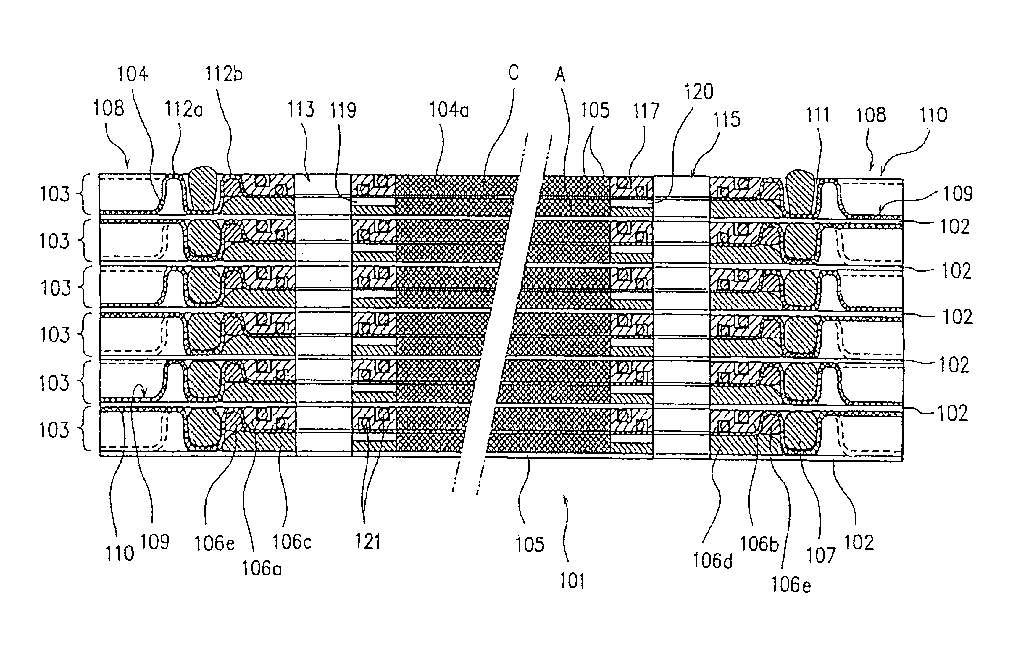
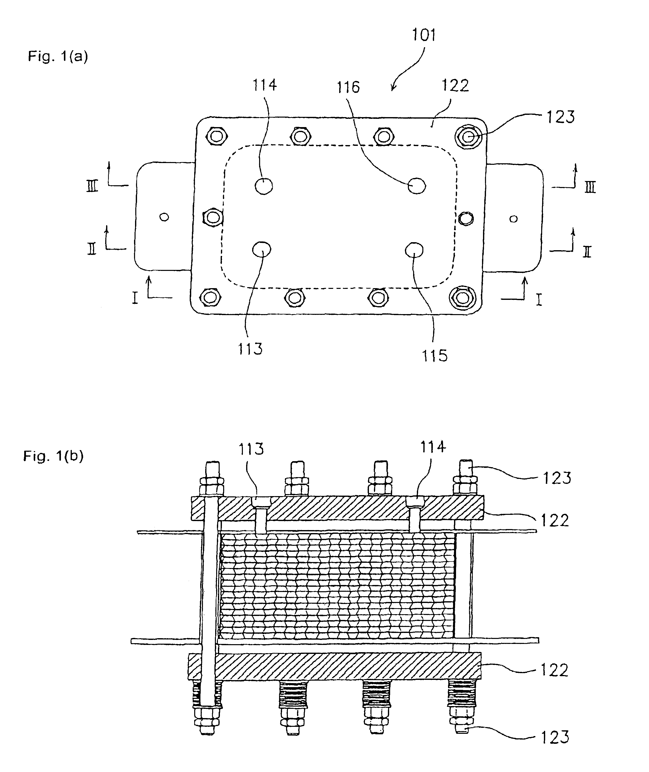
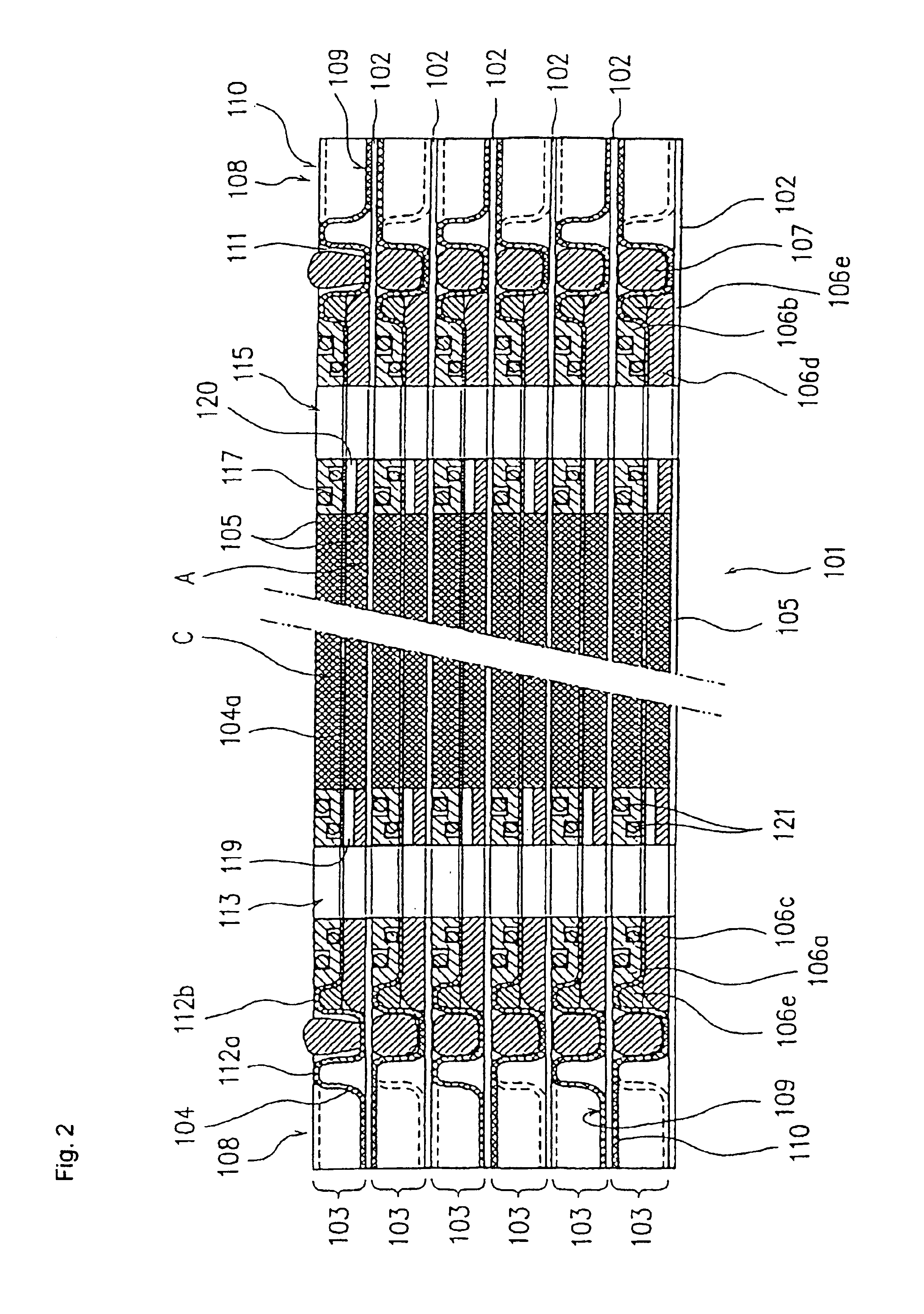
FIG. 1(a) is a plane view illustrating one embodiment of the electrochemical cell according to the first aspect of the present invention. FIG. 1(b) is a side view with a partial cross section as viewed from line I—I in FIG. 1(a), illustrating a part (a honeycomb-like peripheral wall portion) of FIG. 1(a). FIG. 2 is a cross section of an essential portion in a cross-sectional view taken along line II—II in FIG. 1(a). FIG. 3 is a cross section illustrating an essential portion in a cross-sectional view taken along line III—III in FIG. 1(a). FIG. 4(a) is a plane view illustrating one embodiment of the electrode plate according to the first aspect of the present invention. FIGS. 4(b) and 4(c) are cross sections respectively taken along lines IV(B)—IV(B) and IV(C)—IV(C) in FIG. 4(a). FIG. 5 is a perspective view of one embodiment of the electrode plate unit prior to...

Example

Embodiment 2

Now, the electrochemical cell of one embodiment according to the second aspect of the present invention will be described with reference to the drawings.

FIG. 8 is a perspective view illustrating an essential portion of electrochemical cell 201 of this embodiment prior to the assembling thereof. FIG. 9 is a cross section taken along line IX—IX in FIG. 8, illustrating the essential portion of the electrochemical cell 201 of FIG. 8 prior to the assembling thereof FIG. 10 is a perspective view illustrating an electrode plate, a porous electric current supplier and one annular member in the electrochemical cell of FIG. 8. FIG. 11 is a perspective view illustrating an electrode plate, a porous electric current supplier and another annular member in the electrochemical cell of FIG. 8. FIG. 12 is a cross section taken along line XII—XII in FIG. 10. FIG. 13 is a perspective view illustrating an essential portion of another embodiment of the electrochemical cell prior to the assem...

Example

Embodiment 3

Now, the electrochemical cell of one embodiment according to the third and fourth aspects of the present invention will be described with reference to the drawings.

FIGS. 18 are schematic views of electrochemical cell 301 according to this embodiment, in which FIG. 18(a) is a plane view of the electrochemical cell 301, and FIG. 18(b) is a side view with a portion of FIG. 18(a) in section taken along line XVIII—XVIII in FIG. 18(a). FIG. 19 is a cross section illustrating an essential portion of the cross-sectional view taken along line XIX—XIX in FIG. 18(a). FIG. 20 is a cross section illustrating an essential portion of the cross-sectional view taken along line XX—XX in FIG. 18(a). FIG. 21 is a disassembled perspective view of an electrode plate unit constituting the electrochemical cell of this embodiment. The electrochemical cell 301 of this embodiment is formed by using the electrode plate units as illustrated in FIG. 21 and hereinafter-described solid electrolyte memb...


PUM

PropertyMeasurementUnit
Lengthaaaaaaaaaa
Thicknessaaaaaaaaaa
Forceaaaaaaaaaa

Abstract

According to the present invention, there is provided an electrode plate for a water electrolysis device, which is formed from a metal plate having such a thickness as to be capable of being press-formed, and which comprises a flat plate portion, and a peripheral edge portion positioned on the outer side of the flat plate portion and bent so that recesses and protrusions are alternately arrayed along an outer peripheral edge thereof.

Description

FIELD OF THE INVENTIONThis invention relates to an electrochemical cell for water electrolysis, and related parts for the electrochemical cell.A first aspect of the present invention relates to an electrode plate for water electrolysis device, electrode plate unit and electrochemical cell. More specifically, it relates to an electrode plate and electrode plate unit used in a water electrolysis device such as a hydrogen / oxygen generator for generating oxygen gas, hydrogen gas or the like by water electrolysis, as well as an electrochemical cell using this electrode plate unit.A second aspect of the present invention relates to a solid electrolyte membrane unit of a water electrolysis device, and an electrochemical cell. More specifically, it relates to a solid electrolyte membrane unit and an electrochemical cell used in a water electrolysis device such as a hydrogen / oxygen generator for producing high purity hydrogen and oxygen gases by water electrolysis.Third and fourth aspects of...

Claims


Application Information

Patent Timeline
IPC IPC(8): C25B9/20C25B11/00C25B9/18C25B11/02
CPCC25B9/20C25B11/02Y10T29/53204Y10T29/532Y02E60/366C25B9/73Y02E60/36
Inventor TOYOSHIMA, MANABUYONEZAWA, MASARUHIRAI, KIYOSHIMIYAKE, AKIKOISHII, YUTAKAOI, TSUTOMUTORIU, SHINGO
Owner KOBELCO ECO-SOLUTIONS CO LTD
Why Eureka
Try Eureka