Light-emitting element and method of producing the same

a technology of light-emitting elements and light-emitting tubes, which is applied in the direction of thermoelectric devices, semiconductor/solid-state device details, and luminescent compositions, etc., can solve the problems of low light-emitting efficiency, low light-emitting brightness and light-emitting efficiency thereof, and high driving voltage of such elements

Inactive Publication Date: 2005-02-08
FUJIFILM CORP
View PDF3 Cites 66 Cited by
  • Summary
  • Abstract
  • Description
  • Claims
  • Application Information

AI Technical Summary

Problems solved by technology

Conventional organic light-emitting elements have problems that the driving voltage thereof is high, and the light-emitting brightness and light-emitting efficiency thereof are low.
However, such organic light-emitting elements wherein an organic thin film is formed by vapor deposition have a problem that the light-emitting efficiency thereof is far lower than that of inorganic LED elements or fluorescent tubes.
It is therefore impossible to avoid deterioration in the characteristics thereof due to crystallization of the low-molecular compound.
Furthermore, there are problems that costs for production thereof are high, and the production efficiency thereof is low.
However, the above organic light-emitting elements formed by wet film-forming method also have a problem that the element uses fluorescent luminescence obtained from singlet excitons, in the same way as the above organic light-emitting element formed by dry method, to therefore have only low light-emitting efficiency.
However, these inorganic light-emitting elements can give only a brightness of several hundred candelas per square meter, although the driving of the inorganic light-emitting element requires a power source supplying several hundreds of volts or hertz.
Further, the production of the inorganic EL element is not necessarily easy, since it requires using a gas phase method, such as sputtering, to produce its inorganic light-emitting layer, or dispersing particles having a size of several tens of micrometers into a highly dielectric polymer.
However, this material is harmful to both the human body and the environment.

Method used


Image

  • Light-emitting element and method of producing the same
  • Light-emitting element and method of producing the same

Examples


example 1

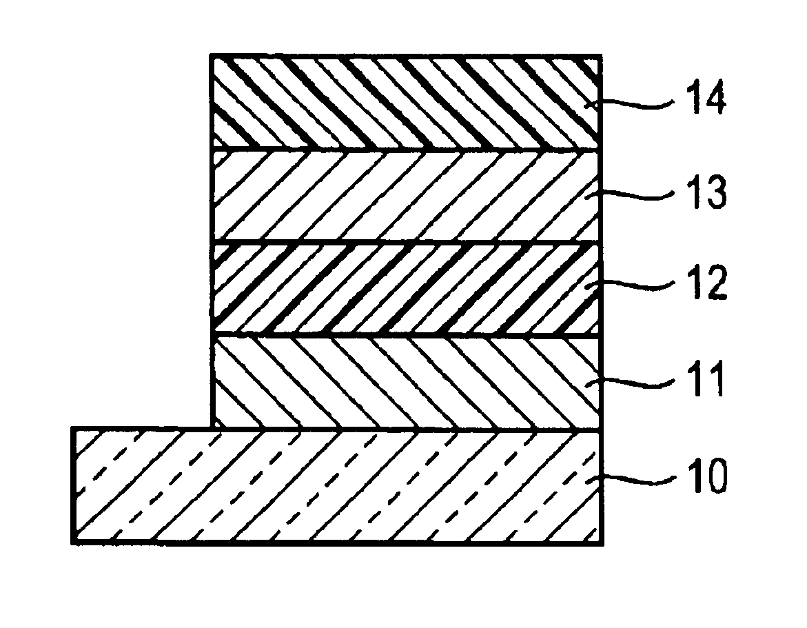
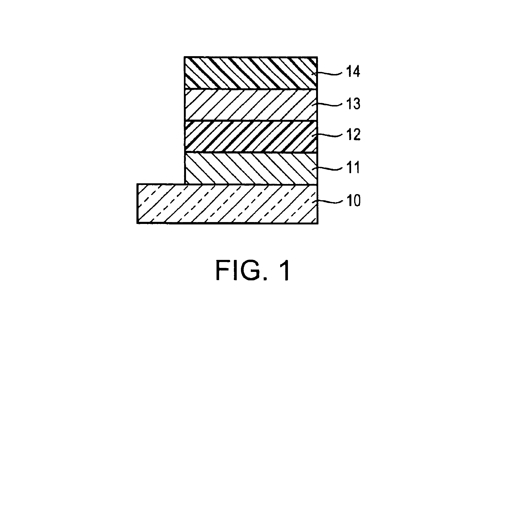
A glass substrate, 0.6 mm in thickness, was cut into 2.5 cm squares, and one of the cut glass substrates was introduced into a vacuum chamber. An ITO target, containing 10% by mass of SnO2, was used to form a transparent electrode, made of an ITO thin film (thickness, 0.2 μm), by DC magnetron sputtering (substrate temperature, 100° C.; oxygen pressure, 1×10⁻³ Pa). The surface resistance of the ITO thin film was 10 Ω / □. The resultant ITO thin film was etched to produce stripes 5 mm in width.

The substrate, on which the transparent electrode was formed, was put into a washing container and washed with IPA (isopropyl alcohol). Thereafter, the substrate was subjected to UV-ozone treatment for 30 minutes. Next, the surface of the transparent electrode was spin-coated with a dispersed product, wherein polyethylene dioxythiophene / polystyrenesulfonic acid was dispersed in water (Baytron P (trade name), manufactured by BAYER AG; solid content, 1.3%), and subsequently the substrate was vacuum-...

example 2

A light-emitting element was prepared in the same manner as Example 1, except that the metal oxide nanoparticles used in the light-emitting layer was changed to Ga2O3 nanoparticles. The light-emission starting voltage of the resultant light-emitting element was 21 V, and was lower than that of the light-emitting element of Comparative Example 1. The luminous color of the light-emitting element of Example 2 was blue, in the same way as that of the light-emitting element of Comparative Example 1. However, when the brightness was 20 cd / m2, the current of the light-emitting element of Example 2 was 9.9 mA, and that of the light-emitting element of Comparative Example 1 was 36.9 mA. It was learned from these results that the light-emitting element of the present invention, in which its light-emitting layer comprised metal oxide nanoparticles, was superior in light-emitting efficiency.

example 3

A solution was prepared by dissolving 1% by mass of poly(2-methoxy-5-(2′-ethyl)hexoxyphenylenevinylene) (MEH-PPV), which was both a conductive polymer and a light-emitting material, in dichloroethane. This was used as a coating solution for a polymer light-emitting layer. A light-emitting element was prepared in the same manner as Example 1, except that a polymer light-emitting layer, 100 nm in thickness, was formed instead of the hole transport layer, and further, a light-emitting layer was formed by applying a colloidal solution in which 4% by mass of ZnO nanoparticles were dispersed in ethanol.


PUM

PropertyMeasurementUnit
thicknessaaaaaaaaaa
thicknessaaaaaaaaaa
particle diameteraaaaaaaaaa

Abstract

A light-emitting element comprising a transparent electrode, a light-emitting layer, and a back electrode, on a substrate, wherein the light-emitting layer comprises photoluminescent metal oxide nanoparticles having an average particle size of 1 to 50 nm; and a method of producing the same.

Description

FIELD OF THE INVENTIONThe present invention relates to a light-emitting element suitable for use as an area light source of a full color display, a backlight, a lighting equipment or the like, or as a light source array of a printer or the like, and to a method of producing the same. The present invention relates particularly to a light-emitting element that is safe and inexpensive and has superior light-emitting efficiency, and to a method of producing the same.BACKGROUND OF THE INVENTIONAn organic electroluminescence element (OLED) using an organic light-emitting material is promising for use as an inexpensive, large-area, solid-state light-emission-type full-color display element or a writing light source array. Many developments thereon have been made. In general, an organic light-emitting element comprises a light-emitting layer and a pair of opposite electrodes between which the light-emitting layer is sandwiched. When an electric field is applied to between the two electrodes...

Claims


Application Information

Patent Timeline
Patent Type & Authority Patents(United States)
IPC IPC(8): H01L51/50H01L33/00H05B33/14B82Y20/00C09K11/00C09K11/54C09K11/62H05B33/10
CPCH01L51/5012H01L33/20H01L51/5088H01L51/5048H10K50/14H10K50/17H10K50/11
Inventor HIRAI, HIROYUKIFUJIMOTO, HIROSHINAKAMURA, SHIGERU
Owner FUJIFILM CORP
Why Eureka
Try Eureka