
Wide-angle lens system

a wide-angle lens and wide-angle technology, applied in the field of wide-angle lens systems, can solve the problems of high negative distortion, significant coma aberration and astigmatism, and high aberration, and achieve the effect of small blurring or distortion, adequate performance, and significant reduction of various types of aberration

Inactive Publication Date: 2005-02-08
ELMO CO LTD
View PDF4 Cites 9 Cited by
  • Summary
  • Abstract
  • Description
  • Claims
  • Application Information

AI Technical Summary

Benefits of technology

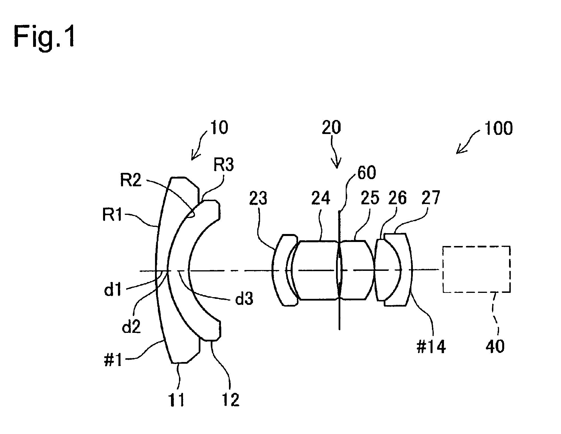
This wide-angle lens system described above may be constructed such that the first lens group comprises a minimum of two lenses, and the variation in the thickness in the radial direction of the second lens comprising a meniscus lens with an aspherical concave surface can be maintained within a narrow range. As a result, in the wide-angle lens system of the present invention, the construction of the first lens group is simple, the manufacturing and assembly of the lenses forming the first lens group is easy, and aberration such as distortion can be kept small.
Glass, synthetic resin or another optical material may be used as the material from which the first and second lenses of the first lens group are formed, so long as the optical requirements regarding the lenses are met. In particular, if the first lens is formed from glass by polishing, it is easy to ensure that the object side surface thereof, which is exposed to the atmosphere, satisfies the durability requirement, and a precise configuration can be achieved by polishing. The second lens of the first lens group may be formed from synthetic resin by molding. Naturally, it may be manufactured by molding glass. Because the image side surface of the second lens is formed as an aspherical surface, if the second lens is manufactured by molding of a translucent material such as resin or glass, the cost and difficulty of manufacturing the second lens, which comprises an aspherical lens, can be reduced.
According to this manufacturing method, the number of lenses comprising the first lens group can be set to a minimum of two, and because the thickness of the second lens having an aspherical concave surface is set to fall within a first prescribed range, the second lens can be manufactured easily. Consequently, the manufacturing process for the wide-angle lens system as a whole can be made simple.
Because the required back focal length can be maintained by the wide-angle lens system comprising the optical device, a CCD camera can be disposed behind the wide-angle lens system. Moreover, images having little aberration can be obtained. In addition, the first lens group of the wide-angle lens system can comprise a minimum of two lenses, and the variation in the thickness in the radial direction of the second lens comprising a meniscus lens with an aspherical concave surface can be maintained within a narrow range. As a result, the construction of the first lens group of the wide-angle lens system is simple, the manufacturing and assembly of the lenses forming the first lens group is easy, and aberration such as distortion can be kept small, enabling sharp, non-blurred images to be obtained.
Because the document display device has a wide-angle imaging area and the imaged object is often a document containing text or the like, the ability to obtain images that have small blurring or distortion offers a considerable advantage.
For the wide-angle lens system of this type of optical device as well, a construction may be adopted wherein where the thickness of the second lens along the optical axis is deemed d0 and the thickness along the normal line at a given distance from the optical axis within the effective radius is deemed (d), the variation in the thickness of the second lens is defined as d / d0, for which the first prescribed range is 0.8 to 1.2 (0.8<d / d0<1.2), the divergence between the radii of curvature of the first and second lenses is defined as R21 / R12, for which the second prescribed range is 0.9 to 1.1 (0.9<R21 / R1<1.1), and the deviation between the difference d2 between the radii of curvature of the first and second lenses along the optical axis and the focal length (f) is defined as d2 / f, for which the prescribed value is 0.2 (d2 / f<0.2). In the wide-angle lens system in which each value is controlled within the value ranges described above, the various types of aberration can be reduced significantly. For example, distortion can be limited to ±2% or less and astigmatism can be limited to ±0.05 mm or less within the effective radius of the second lens. Therefore, it can be ensured that the optical device offers adequate performance.

Problems solved by technology

However, the retrofocus type wide-angle lens system has the problem of high negative distortion, and depending on the lens selection and design, it also entails the problems of significant coma aberration and astigmatism.
As shown in the figure, aberration, particularly distortion, is extremely high in this type of lens system, and a substantial amount of distortion occurs in the captured image in the periphery of the imaging area.
While these types of aberration can be eliminated to some extent using such methods as increasing the number of lenses or making a lens surface aspherical, if the number of lenses is increased, the construction becomes complex, making the lens system more difficult and costly to manufacture.
Where an aspherical lens is to be used in order to efficiently correct for distortion, because the lens configuration entails significant variation in lens thickness from the optical axis to the periphery of the lens, it is difficult to manufacture the lens with precision.

Method used


Image

  • Wide-angle lens system
  • Wide-angle lens system
  • Wide-angle lens system

Examples


first embodiment

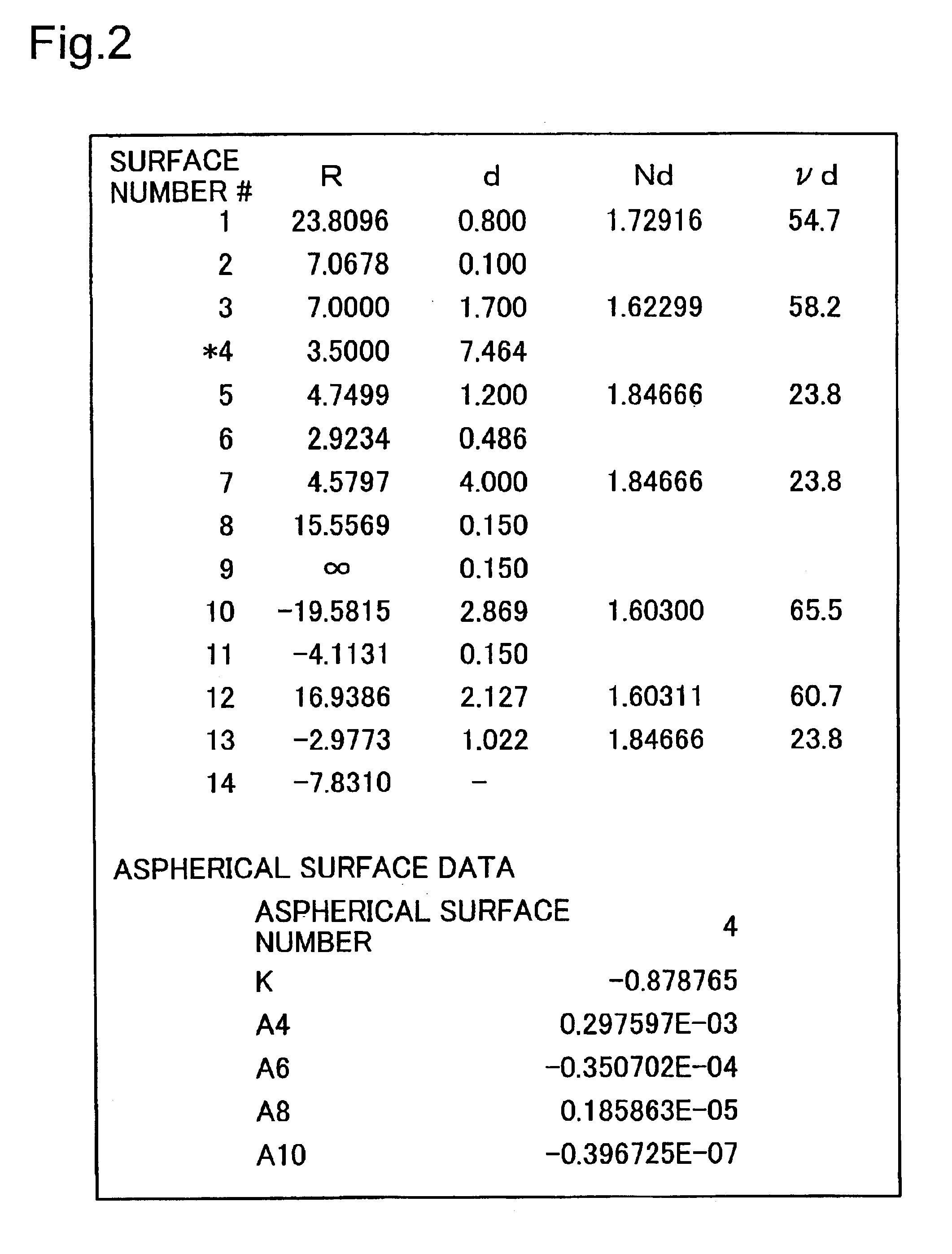
FIG. 4 shows the various characteristics of the wide-angle lens system 100 of the first embodiment having the above construction. In FIG. 4, (A) shows the amount of spherical aberration in relation to the F-number, and (B) shows the amount of vertical astigmatism in the image forming surface. The symbols (C), (e) and (g) in FIG. 4(A) indicate the different light wavelengths used in order to seek the respective aberrations (C-line: 656.3 nm, e-line: 546.1 nm, g-line: 435.8 nm). The symbol T in FIG. 4(B) indicates that the characteristic pertains to tangential light rays, while the symbol S indicates that the characteristic pertains to sagittal light rays (and this shall apply to the discussion below as well). FIG. 4(C) shows the amount of vertical distortion in the image forming surface. The same symbols are used in FIG. 14 showing the characteristics of the conventional wide-angle lens system. However, the horizontal axes in FIGS. 4(C) and 14(C) indicate the amount of distortion. In...

second embodiment

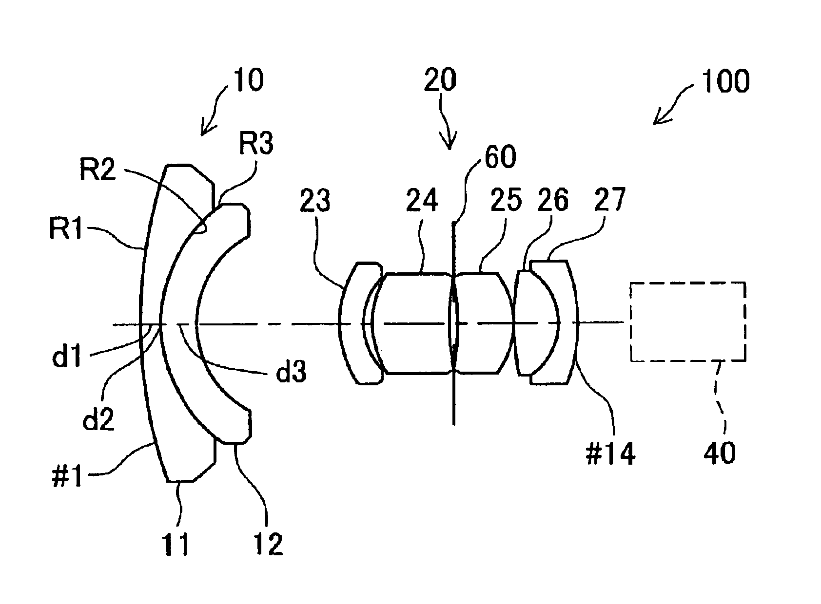
the present invention will now be described. As shown in FIG. 5, the wide-angle lens system 200 of the second embodiment comprises a first lens group 110 (lenses 111 and 112) and a second lens group 120 (lenses 123 through 127), and the lenses comprising these lens groups are essentially identical to those described in connection with the first embodiment. The wide-angle lens system 200 of the second embodiment is designed for use in a so-called ½″ CCD camera 140, and the basic constructions of the lens groups are essentially identical to those described in connection with the first embodiment. FIG. 6 shows various parameters pertaining to the lenses of the second embodiment. The symbols used therein are identical to the symbols used in connection with the first embodiment. The focal length (f) for all lens groups of the wide-angle lens system 200 is 4.0 mm, the F-number is 3.0, and the half-field angle is 45.1°. The values for d / d3, R3 / R2, d2 / f and the like are identical to those i...

third embodiment

the present invention will now be described. FIG. 8 shows the lens construction of a wide-angle lens system 300 of the third embodiment, which is designed for use in a so-called ⅓″ CCD camera 240. As shown in the figure, the basic constructions of the lens groups of the wide-angle lens system 300 comprising a first lens group 210 (lenses 211 and 212) and a second lens group 220 (lenses 223 through 227) are identical to the constructions employed in the first and second embodiments except that the second lens 212 is made of synthetic resin, but in this embodiment, a variable aperture mechanism 260 is disposed at the aperture position of the second lens group 220. Whereas the aperture 60 in the first and second embodiments was a fixed aperture with a small thickness, the variable aperture mechanism 260 is thicker due to incorporation of the variable aperture mechanism. As a result, in this embodiment, the distance d8 separating the aperture 60 (i.e., the surface #9) from the lens surf...


PUM


Abstract

A wide-angle lens system having a long back focal length, disposed in front of a ⅓″ CCD camera and the focal length (f) for all lens groups is 3.0 mm, the F-number is 3.0 and the half-field angle is 46°. The following conditions are met by the first lens group: 1≦d / d3<1.2; R3 / R2=0.99; and d2 / f=0.03. Here, (d) indicates the thickness of the second lens along the normal line at a given distance from the optical axis within the maximum effective diameter of the object side convex surface of the lens. d3 is the thickness of the second lens along the optical axis.

Description

BACKGROUND OF THE INVENTION1. Field of the InventionThe present invention relates to a wide-angle lens system, as well as to a manufacturing method therefor and to optical devices in which the wide-angle lens system is used, and more particularly to a wide-angle lens system that includes a first lens group that is located on the object side and has an overall negative refractive power and a second lens group that is located on the image side of the first lens group and has an overall positive refractive power, as well as to a technology pertaining thereto.2. Description of the Related ArtWide-angle lens systems that have a large imaging area are used not only for a special purpose, such as for use as a fish-eye lens, but are widely used in the imaging systems of such devices as document display devices that obtain images of documents from a relatively close distance. The required specifications for such wide-angle lens systems include not only a large imaging area, but also adequate...

Claims


Application Information

Patent Timeline
Patent Type & Authority Patents(United States)
IPC IPC(8): G02B13/04G02B13/18
CPCG02B13/04
Inventor KONDO, YASUHIROYAMADA, KAZUYOSHI
Owner ELMO CO LTD
Learn More