Laser spectral engineering for lithographic process

a technology of lithographic process and laser spectral engineering, applied in the direction of beam/ray centering arrangement, active medium material, instruments, etc., can solve the problems of image blurring, additional overlay (image placement) errors, and inability to adjust for wavelength variations, so as to improve the pattern resolution of photo resist film

Inactive Publication Date: 2005-02-08
CYMER INC
View PDF58 Cites 69 Cited by
  • Summary
  • Abstract
  • Description
  • Claims
  • Application Information

AI Technical Summary

Benefits of technology

The present invention provides an integrated circuit lithography technique called spectral engineering by Applicants, for bandwidth control of an electric discharge laser. In a preferred process, a computer model is used to model lithographic parameters to determine a desired laser spectrum needed to produce a desired lithographic result. A fast responding tuning mechanism is then used to adjust center wavelength of laser pulses in a burst of pulses to achieve an integrated spectrum for the burst of pulses approximating the desired laser spectrum. The laser beam bandwidth is controlled to produce an effective beam spectrum having at least two spectral peaks in order to produce improved pattern resolution in photo resist film. Line narrowing equipment is provided having at least one piezoelectric drive and a fast bandwidth detection control system having a time response of less than about 2.0 millisecond. In a preferred embodiment, a wavelength tuning mirror is dithered at dither rates of more than 500 dithers per second in phase with the repetition rate of the laser. In one case, the piezoelectric drive was driven with a square wave signal and in a second case it was driven with a sine wave signal. In another embodiment, the maximum displacement was matched on a one-to-one basis with the laser pulses in order to produce a desired average spectrum with two peaks for a series of laser pulses. Other preferred embodiments utilize three separate wavelength tuning positions producing a spectrum with three separate peaks. In another preferred embodiment, effective bandwidths in the range of 0.4 pm to 2.0 pm are produced in a series of pulses (such as a 30-pulse window of pulses).

Problems solved by technology

The etalon creates an interference pattern having concentric bands of dark and light levels due to destructive and constructive interference by the laser light.
The limitations of acceptable optical lens materials to fused silica and calcium fluoride for use with deep ultraviolet light at 248 nm and 193 nm wavelengths have meant that projection lenses for KrF and ArF lithography, to a large degree, cannot be corrected for wavelength variations.
However, recently integrated circuit manufacturers have noticed that the quality of their integrated circuits can be adversely affected by bandwidths, such as about 0.35 pm FWHM, which are substantially narrower than the bandwidths for which their optical systems were designed.
Several difficulties result from this FLEX process with both step and scan as well as step and repeat exposure implementations.
Multiple pass exposure results in additional overlay (image placement) errors and image blurring.

Method used


Image

  • Laser spectral engineering for lithographic process
  • Laser spectral engineering for lithographic process
  • Laser spectral engineering for lithographic process

Examples


Embodiment Construction

Simulation

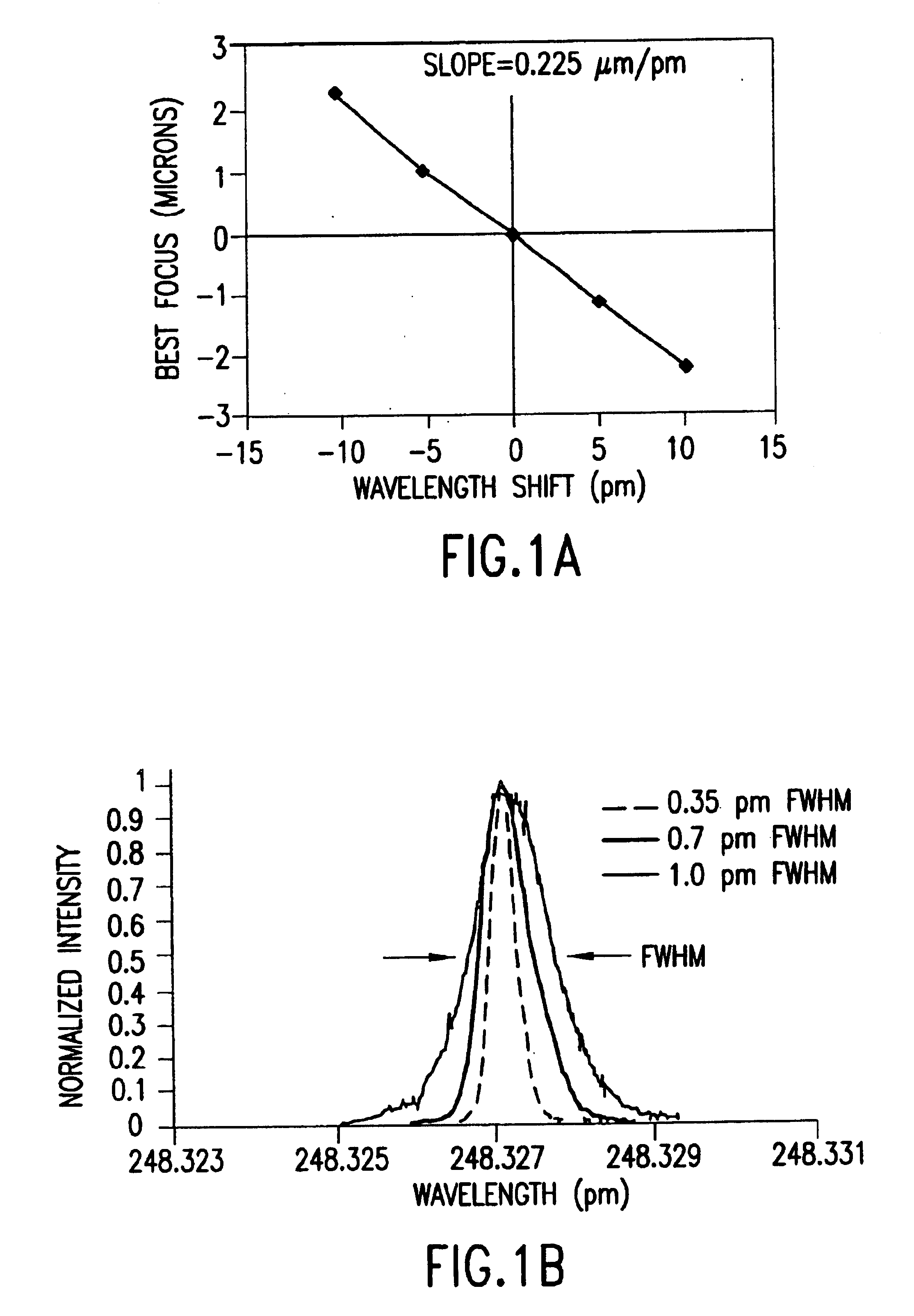
Simulation of the effects of wavelength and bandwidth changes have been performed by Applicants. The main effect of changing the exposure wavelength for a non-chromatic corrected lens is a change in the position of the focal plane. Over a fairly wide range of wavelengths, this change in focus is approximately linear with the change in the nominal wavelength (i.e., the central wavelength of the illumination spectrum). The wavelength response of a lens can be determined experimentally by manually changing the central wavelength of the laser and using the imaging sensor of the stepper to monitor the shift in focus that results. FIG. 1A shows an example of such a measurement.

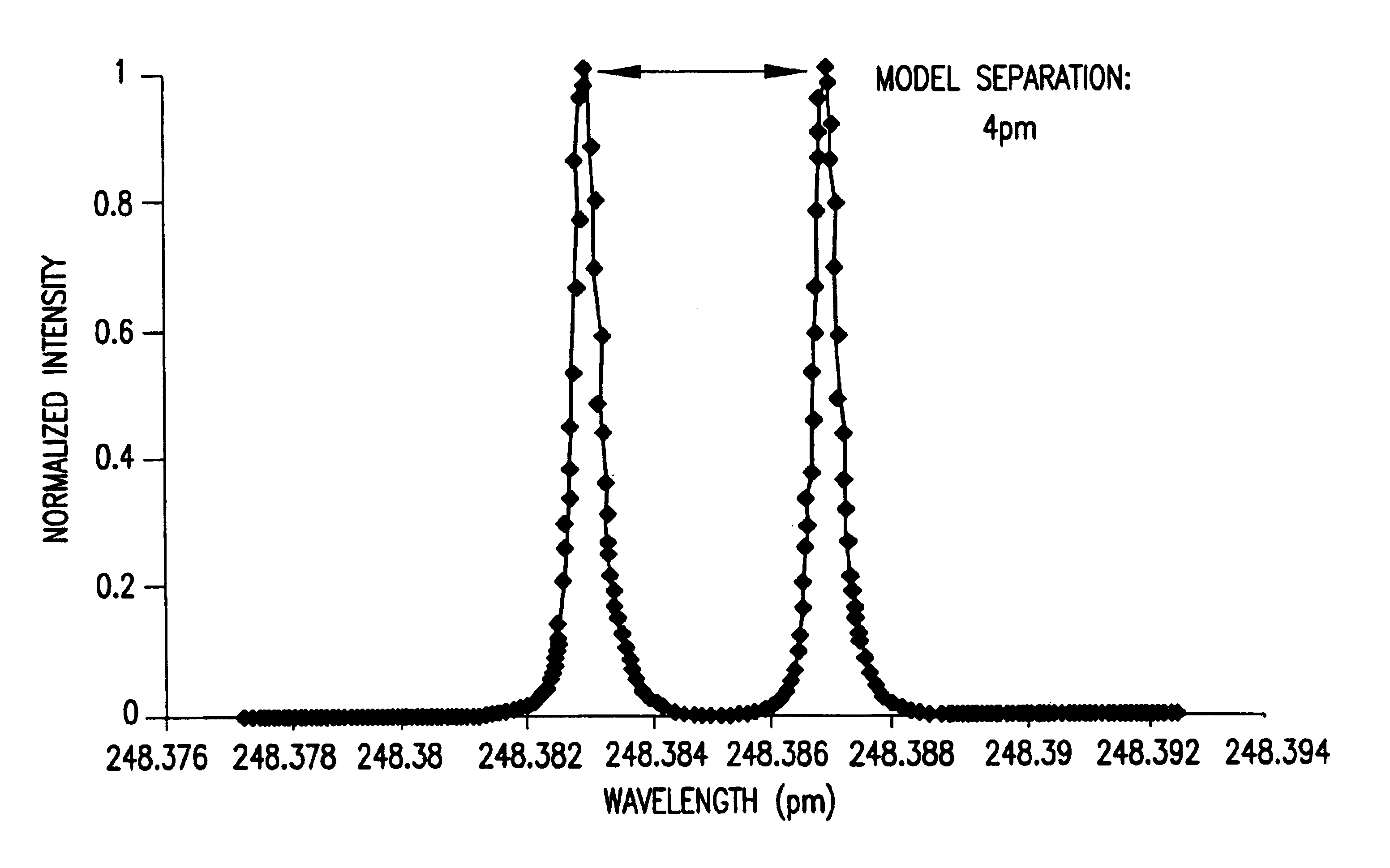
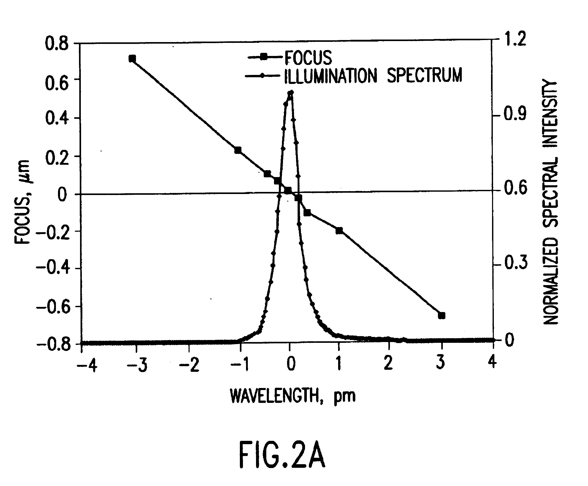
Given the change in focus with change in wavelength, the use of a broadband illumination spectrum means that each wavelength in the spectrum will produce an aerial image with a different best focus. The total aerial image will be a sum of the aerial images at each focal position, weighted by the relative i...


PUM

PropertyMeasurementUnit
wavelengthsaaaaaaaaaa

Abstract

An integrated circuit lithography technique called spectral engineering by Applicants, for bandwidth control of an electric discharge laser. In a preferred process, a computer model is used to model lithographic parameters to determine a desired laser spectrum needed to produce a desired lithographic result. A fast responding tuning mechanism is then used to adjust center wavelength of laser pulses in a burst of pulses to achieve an integrated spectrum for the burst of pulses approximating the desired laser spectrum. The laser beam bandwidth is controlled to produce an effective beam spectrum having at least two spectral peaks in order to produce improved pattern resolution in photo resist film. Line narrowing equipment is provided having at least one piezoelectric drive and a fast bandwidth detection control system having a time response of less than about 2.0 millisecond. In a preferred embodiment, a wavelength tuning mirror is dithered at dither rates of more than 500 dithers per second in phase with the repetition rate of the laser. In one case, the piezoelectric drive was driven with a square wave signal and in a second case it was driven with a sine wave signal. In another embodiment, the maximum displacement was matched on a one-to-one basis with the laser pulses in order to produce a desired average spectrum with two peaks for a series of laser pulses. Other preferred embodiments utilize three separate wavelength tuning positions producing a spectrum with three separate peaks.

Description

FIELD OF THE INVENTIONBackground of the InventionWavelength ControlLasers are used for many applications. For example, lasers, such as KrF and ArF excimer lasers, are used in stepper and scanner equipment for selectively exposing photoresist in a semiconductor wafer fabrication process. In such fabrication processes, the optics in the steppers and scanners are designed for a particular wavelength of the laser. The laser wavelength may drift over time and, thus, a feedback network is typically employed to detect the wavelength of the laser and correct the wavelength as necessary.In one type of feedback network used to detect and adjust the wavelength of a laser, an etalon receives a portion of the emitted light from the laser. The etalon creates an interference pattern having concentric bands of dark and light levels due to destructive and constructive interference by the laser light. The concentric bands surround a center bright portion. The diameter of a light band produced by an e...

Claims


Application Information

Patent Timeline
Patent Type & Authority Patents(United States)
IPC IPC(8): G03F7/20H01S3/14H01S3/13H01S3/223H01S3/225H01S3/036H01S3/105H01S3/104H01S3/038H01S3/1055H01S3/08H01S3/134H01S3/097H01S3/0971H01S3/04H01S3/22H01S3/11H01S3/139H01S3/041H01S3/102H01S3/0975B41CB41C1/00H01L21/027H01S3/081H01S3/10H01S3/137
CPCG03F7/70025G03F7/70333G03F7/70575G03F7/70933H01S3/036H01S3/0385H01S3/104H01S3/105H01S3/13H01S3/223H01S3/225G03F7/70041H01S3/2258H01S3/038H01S3/0404H01S3/041H01S3/08009H01S3/08036H01S3/0812H01S3/097H01S3/0971H01S3/0975H01S3/1024H01S3/1055H01S3/1305H01S3/134H01S3/139H01S3/22H01S3/2207H01S3/2251H01S3/2256
Inventor SPANGLER, RONALD L.LIPCON, JACOB P.RULE, JOHN A.JACQUES, ROBERT N.KROYAN, ARMENLALOVIC, IVANFOMENKOV, IGOR V.ALGOTS, JOHN M.
Owner CYMER INC
Why Eureka
Try Eureka