The indirect evaporative cooling processes of the present patent disclosure also employ indirect evaporative cooling apparatus having a dry side channel and a wet side channel that are separated by a heat exchange plate. They too are used to cool a fluid such as a gas (e.g., air) and / or a liquid (e.g., water). It might also be noted here that by use of the term “plate”, applicants do not intend to limit the contour of the surface of the heat exchange plate to a flat shape. Indeed, the term plate may be taken to mean any shape including curved, spiraled, corrugated or otherwise contoured shape that meets the requirements of a particular installation. Applicants' apparatus, and the indirect evaporative cooling processes carried out by them, also serve to reduce the temperature of an incoming gas
stream (e.g., a
stream of air,
nitrogen,
carbon dioxide,
industrial waste gas, etc.). The processes and apparatus of the present patent disclosure are, however, capable of producing gas temperatures that come relatively closer to the
dew point temperature of the gas with far less pressure drop than produced by the previously discussed Maisotsenko processes. This all goes to say that applicants' methods use relatively lower pressure drops and produce higher operating efficiencies. These higher operating efficiencies imply lower operating costs.
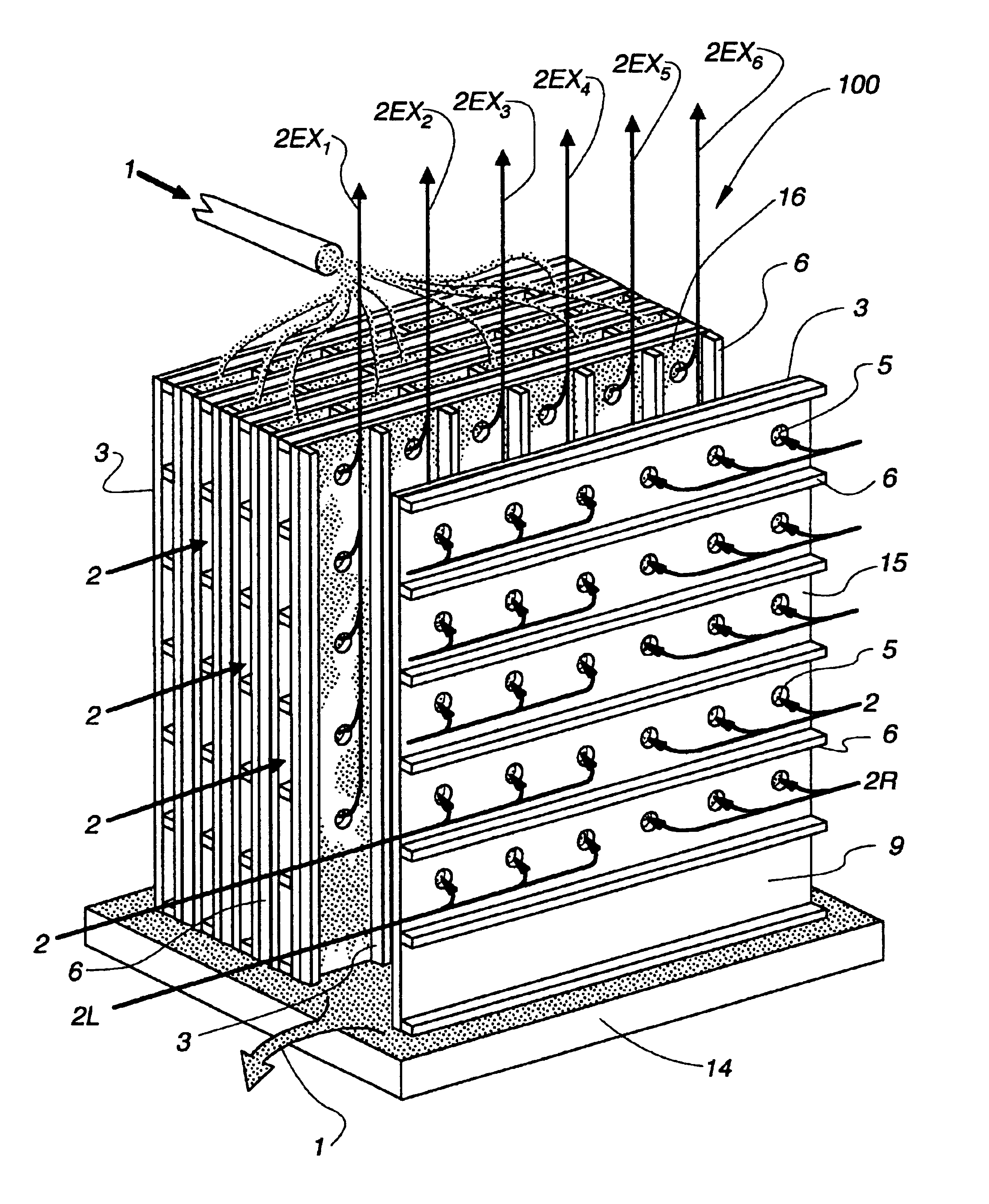
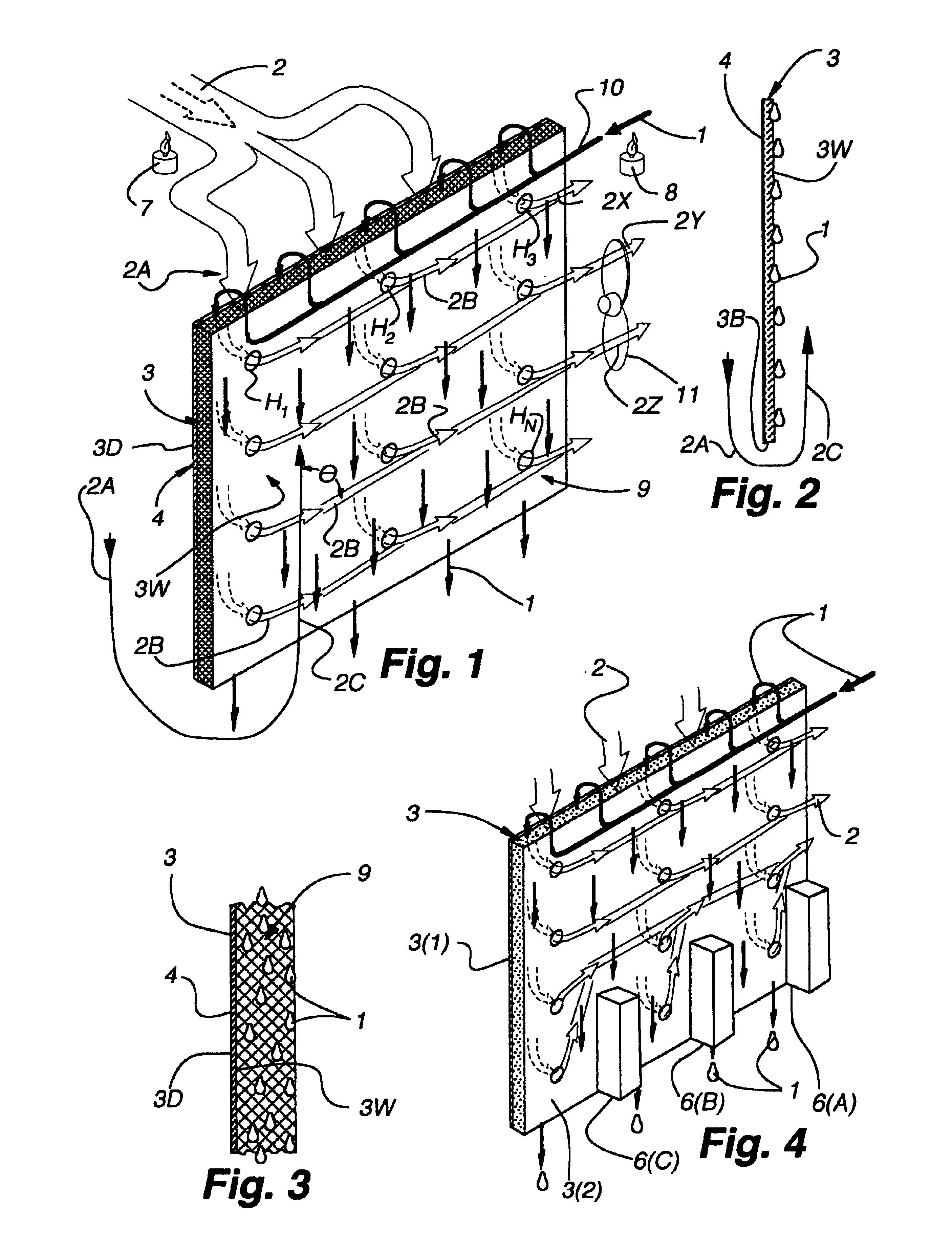
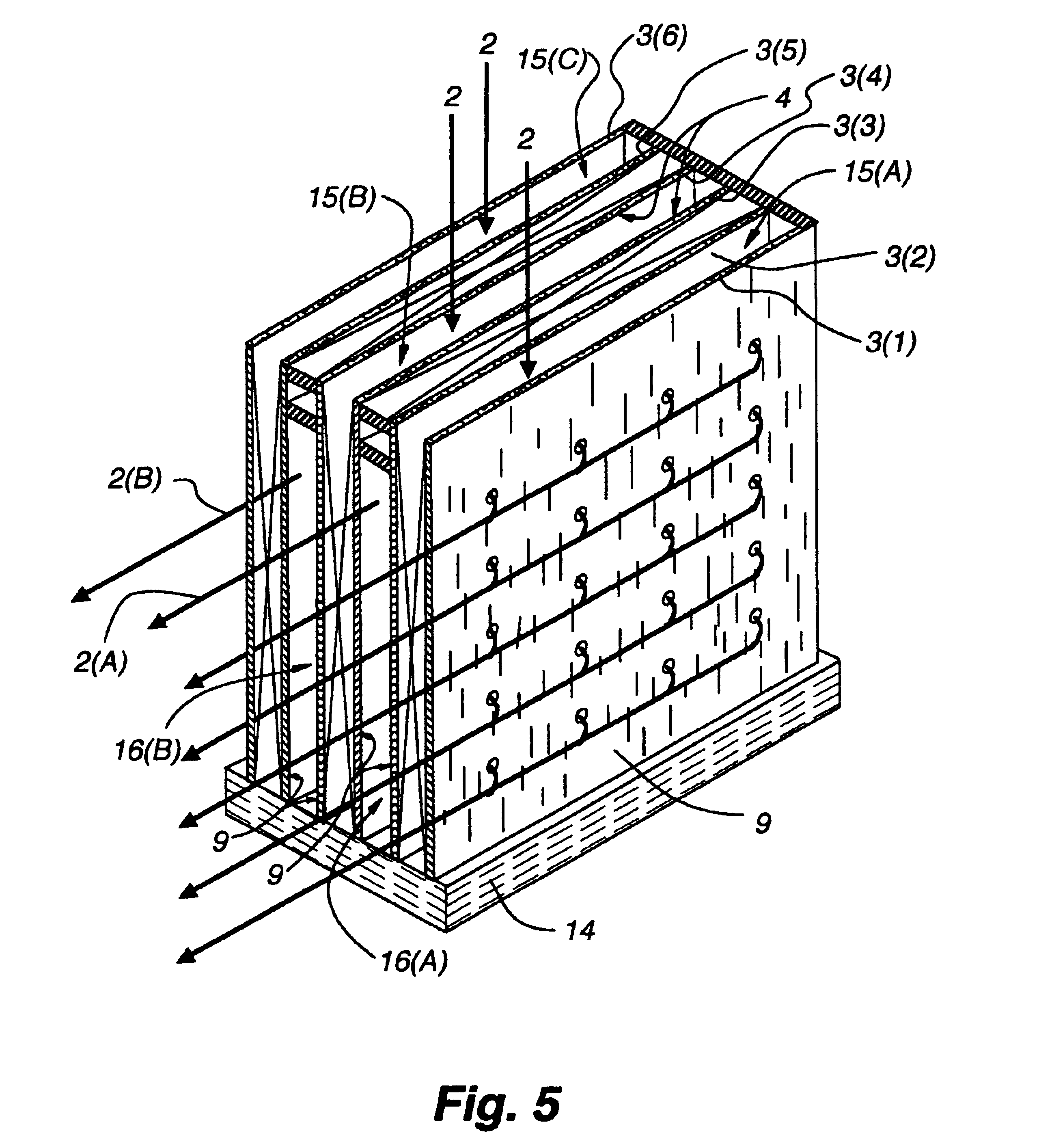
Applicants' relatively lower gas and evaporative liquid temperatures are produced by passing a portion of an incoming gas stream through the body of applicants' heat exchange plate—rather than passing all of the incoming gas around the lower edge of that plate. The portion of the incoming
gas passing through applicants' plate also is, to varying degrees, pre-cooled by contact with preceding portions of the cooled dry side surface of the heat exchange plate. Upon passing through the plate, this portion of the incoming gas enters the wet side channel. Therefore, the processes and apparatus of the present patent disclosure differ from those of the Maisotsenko patents in that a portion (e.g., from about 5% to 100%) of the incoming air flowing through applicants' dry side channel is forced through an array of holes, perforations, micro sieves and / or air permeable regions in the body of the heat exchange plate—and then on into the wet side channel. That is to say that the holes permit fluid communication between the dry side channel and the wet side channel. For the purposes of this patent disclosure all such holes, perforations, micro sieves, openings, areas of gas permeability, etc. in applicants' heat exchange plate will be referred to as “holes” regardless of their size, geometries, spacings, etc. The remainder of applicants' incoming gas (e.g., 95% to 0% of the original volume of incoming gas) will, most preferably, pass around the heat exchange plate (e.g., around the edge) and then also enter the wet side channel. These holes also allow better distribution of air flow than the previously discussed methods. They also give more flexibility in manufacturing and in cooling product gases and various product fluids.
The evaporative liquid (e.g., water) on the wet side of applicants' heat exchange plate will naturally move downward, under the influence of gravity, along a hard smooth face surface of a
solid, sheet-like heat exchange plate. In other preferred embodiments of this invention, however, the evaporative liquid will move downwardly in the body of an
absorbent material that is associated with a
solid, impermeable sheet-like material (such as a sheet of plastic—albeit a sheet of plastic having holes in it) to produce a two layered (e.g., laminated) plate. For example, one side of such a two layered plate can be formed from a sheet of waterproof or
low permeability material such as plastic,
metal,
ceramic, etc. while the other layer of such a two layered plate will comprise a wettable material (such as
cellulose, burlap, etc.) that can readily absorb the evaporative liquid being employed and hold said liquid in relatively prolonged contact with the wet side surface of the
solid, impermeable layer of the plate.
Various evaporative liquid distribution systems can be employed to provide appropriate amounts, forms (films, droplets, etc.) and flow direction for the evaporative liquid e.g., (1) flow along an impermeable wet side surface of a plate and / or (2) flow within a
system of void spaces in a porous, laminate layer of a two or more layered plate. Various tradeoffs are in play here. For example, movement of the evaporative liquid along a smooth, solid wet surface of a single solid sheet can be accomplished with less expensive plate materials and with lower operating costs. On the other hand, movement of such a liquid in an
absorbent material within the body of a two layered plate implies greater plate manufacturing costs as well as greater operating costs. However, plates having an
absorbent material layer require relatively less surface area. This decreased surface area may be worth the material and / or operating costs price paid for it—if
work space volume considerations are especially important. Use of absorbent material
layers in multi-layered heat exchange plates also will facilitate attainment of relatively lower gas temperatures and, hence, higher operating efficiencies.
It might also be noted here that the theoretical limitation of the hereindisclosed methods and apparatus for indirect evaporative cooling is the
dew point temperature of the subject gas (e.g., air). Thus, if the incoming gas 2 is dehumidified, a lower
dew point temperature can be realized. This can be done by applying a solid or
liquid desiccant to the dry side surface of various sheet exchange plates. By dehumidifying the incoming air 2 during the process of pre-cooling that air, the heat of adsorption or absorption associated with the dehumidifying process is removed through the body of the heat exchange plate. This heat removal also serves to increase the efficiency of the desiccants because, in general, desiccants (wet or dry) will adsorb or absorb
moisture better at lower temperatures.
The hereindescribed indirect evaporative cooling process also can be adapted to continually regenerate a solid or
liquid desiccant and thereby reduce the cost of a
desiccant regeneration function. In yet another preferred embodiment of this invention, the evaporative liquid employed in the wet side channel is itself a
liquid desiccant. In other words, such a liquid can serve the evaporative liquid function as well as a
desiccant function. In yet another preferred embodiment of this invention (and especially those employed in
high humidity environments), the incoming gas and / or the incoming evaporative liquid(s) are heated before they enter applicants' indirect evaporative cooling apparatus. Heat from compressors, motors or power
plant waste heat sources may be readily employed for these heating operations.

