Prechamber combustion system

a combustion system and pre-combustion chamber technology, which is applied in the direction of combustion engines, machines/engines, cylinders, etc., can solve the problems of reducing the cranking speed of the engine, preventing the use of glow plug starter aids, and increasing the parasitic loss of the larger capacity pump, so as to reduce the pumping loss and improve the air flow

Inactive Publication Date: 2005-02-15
REGUEIRO JOSE FRANCISCO
View PDF9 Cites 43 Cited by
  • Summary
  • Abstract
  • Description
  • Claims
  • Application Information

AI Technical Summary

Benefits of technology

For the subject improved design for the bottom wall of the prechamber tip, it has been found that a cup-like shape is essential. The cup-shape can be either as hemisphere or a section of a hemisphere. The hemispherical section presents a larger surface at the bottom of the prechamber tip than a flat or only slightly curved portion. The larger surface allows either more circumferentially spaced transfer passages or increased diameter passages to improve air flow and reduce pumping losses. An additional benefit of the hemispherical design is the improved opportunity to align the transfer passages at a desired radial angle with respect to the centerline of the prechamber structure. Also, machining of the passages can be accomplished at a more normal angle to the hemispherical surface of the tip. The additional volume and surface of the tip portion also permits use of an extra tapered transfer passage disposed in the center of the cup-shaped tip, essentially aligned with the centerline of the prechamber body. This is particularly useful in association with a piston configured with a deep central bowl which pistons are often used in larger diesel engines. The benefits of this new design will be discussed hereinafter.
A further object of the invention is to provide a precombustion chamber which increases the mass of products of combustion in the precombustion chamber for discharge into a deep bowl of an associated piston, thus lowering the temperature on the periphery of the piston's crown and reducing the temperature of the piston rings while decreasing headland crevice height and volume thus improving the engine's startability and reducing fuel consumption, emissions, smoke, and noise.

Problems solved by technology

They also usually preclude the use of glow plug starter aids.
The subject new design for the prechamber and combustion system does not anticipate use of such glow plugs as a starter aid in all cases.
Typically, these cooling passages in the piston are formed by an expensive process called “salt-core” casting using a core of salt soluble in water so as to be easily dissolved after the piston is cast.
The larger capacity pump increases parasitic losses.
The losses are particularly undesirable during cold starting where the cold oil increases the load on the oil pump out of proportion resulting in a reduction of the engine's cranking speed.

Method used


Image

  • Prechamber combustion system
  • Prechamber combustion system
  • Prechamber combustion system

Examples


Embodiment Construction

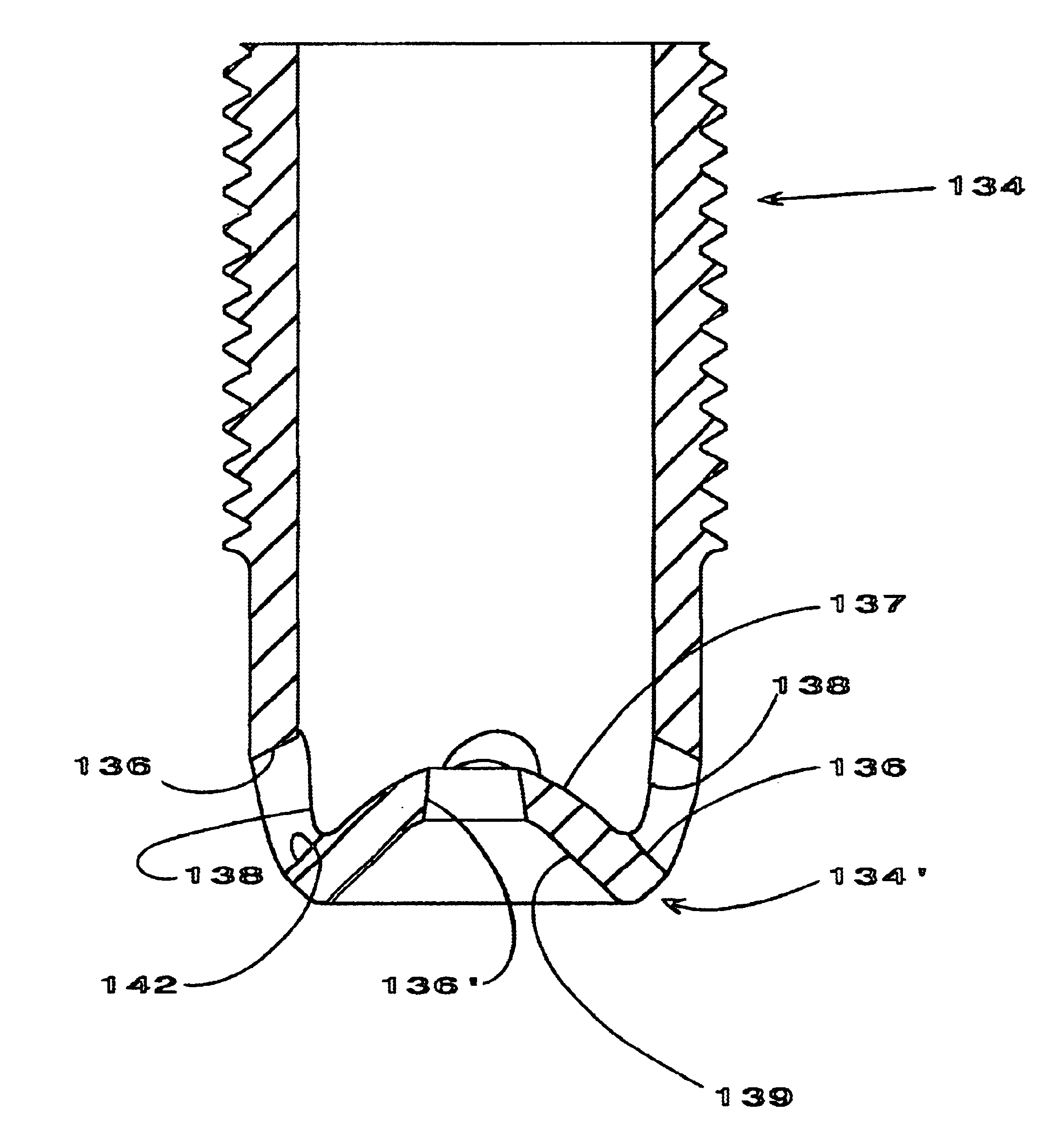
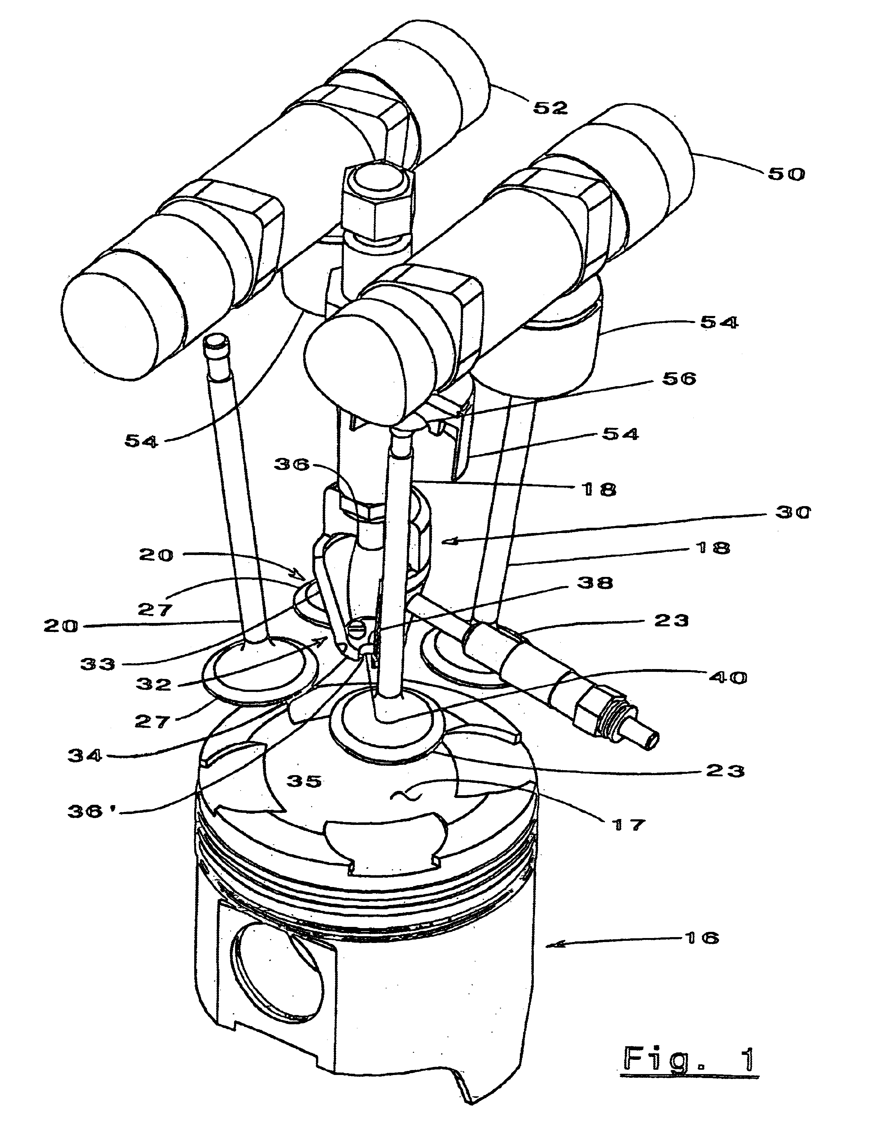
Referring specifically to FIG. 1, a combustion chamber for a large diesel engine is defined including a piston 16 adapted to reciprocate in a cylinder bore (not shown). Although not shown, a crankshaft and connecting rod are operatively connected to the piston 16 as is conventional in such engines. It should be understood that though only one combustion system is shown, an engine would likely include multiple combustion chambers. A valve timing mechanism includes two camshafts 50 and 52 with axes extending in the longitudinal direction of the engine. Intake camshaft 50 and exhaust camshaft 52 rotate to operate respectively a pair of intake valves 18 and a pair of exhaust valves 20 located in the associated cylinder head (not shown).

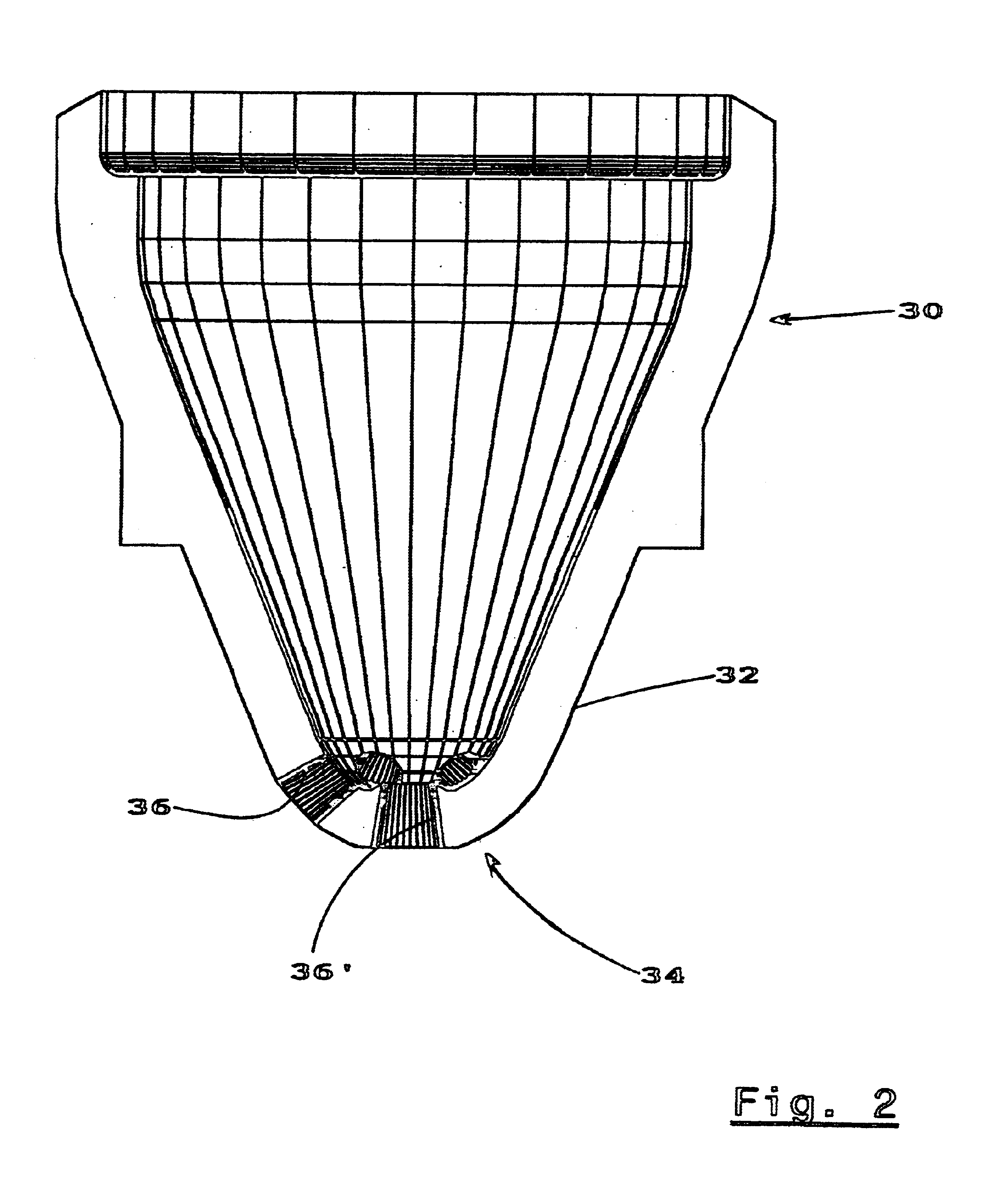
The piston 16, associated cylinder, and associated cylinder head define a main combustion chamber 35 above the piston 16 which defines the bottom wall thereof. The side walls of the combustion chamber 35 are defined by the engine's cylinder bore and the u...


PUM


Abstract

An improved combustion system particularly for a larger type diesel engine featuring a prechamber with a generally cup-shaped bottom tip portion facing the engine's main combustion chamber and with a central transfer passage substantially aligned with the centerline of the prechamber and a plurality of additional transfer passages circumferentially arranged about the centerline of the prechamber. The improved complete combustion system uses a piston with a deep bowl formed in the piston crown into which the central transfer passage directs a strong direct charge of products of combustion from the prechamber.

Description

TECHNICAL FIELDThis invention relates to internal combustion engines and more particularly to diesel engines having a pre-combustion chamber.BACKGROUND OF THE INVENTIONThe U.S. Pat. No. 5,392,744 to Regueiro, entitled “Precombustion Chamber for a Double Overhead Camshaft Internal Combustion Engine” which issued Feb. 28, 1995, discloses a prechamber construction for a diesel engine in which a plurality of transfer passages are formed in the bottom of the prechamber. The passages are circumferentially spaced about the prechamber's centerline and the longitudinal axis of each passage is inclined with respect to the centerline to provide rotation of the air about the centerline. Each passage is tapered with a narrow end opening to the prechamber and a larger end opening to the engine's combustion chamber. The two ends of a passage extend circumferentially about the prechamber's centerline and situated about 90 degrees from one another. One purpose of the tapered and circumferentially al...

Claims


Application Information

Patent Timeline
Patent Type & Authority Patents(United States)
IPC IPC(8): F02B19/18F02B23/02F02B23/04F02B19/00F02B19/08F02F1/42
CPCF02B19/08F02B19/18F02F1/4214F02B23/04Y02T10/125F02B2275/18Y02T10/12
Inventor REGUEIRO, JOSE FRANCISCO
Owner REGUEIRO JOSE FRANCISCO
Why Eureka
Try Eureka