Subsea wellbore drilling system for reducing bottom hole pressure

a wellbore and bottom hole technology, applied in the direction of wellbore/well accessories, sealing/packing, vessel construction, etc., can solve the problems of increasing the concentration of solids, not being used in practical application, and increasing the ecd of return fluid even greater than the static mud weight, so as to achieve faster and more effective subsea downhole operations, the effect of rapid deploymen

Inactive Publication Date: 2005-02-15
BAKER HUGHES INC
View PDF17 Cites 86 Cited by
  • Summary
  • Abstract
  • Description
  • Claims
  • Application Information

AI Technical Summary

Benefits of technology

These features (in some instances acting individually and other instances acting in combination thereof) regulate the fluid pressure in the borehole at predetermined values during subsea downhole operations in the wellbore by operating the adjustable pump system to overcome at least a portion of the hydrostatic pressure and friction loss pressure of the return fluid. Thus, these features enable the downhole pressure to be varied through a significantly wider range of pressures than previously possible, to be adjusted far faster and more responsively than previously possible and to be adjusted for a wide range of applications (i.e...

Problems solved by technology

The situation is worsened when liquid circulation losses are included, thereby increasing the solids concentration and creating an ECD of the return fluid even greater than the static mud weight.
Another method for changing the density gradient in a deepwater return fluid path h...

Method used


Image

  • Subsea wellbore drilling system for reducing bottom hole pressure
  • Subsea wellbore drilling system for reducing bottom hole pressure
  • Subsea wellbore drilling system for reducing bottom hole pressure

Examples


Embodiment Construction

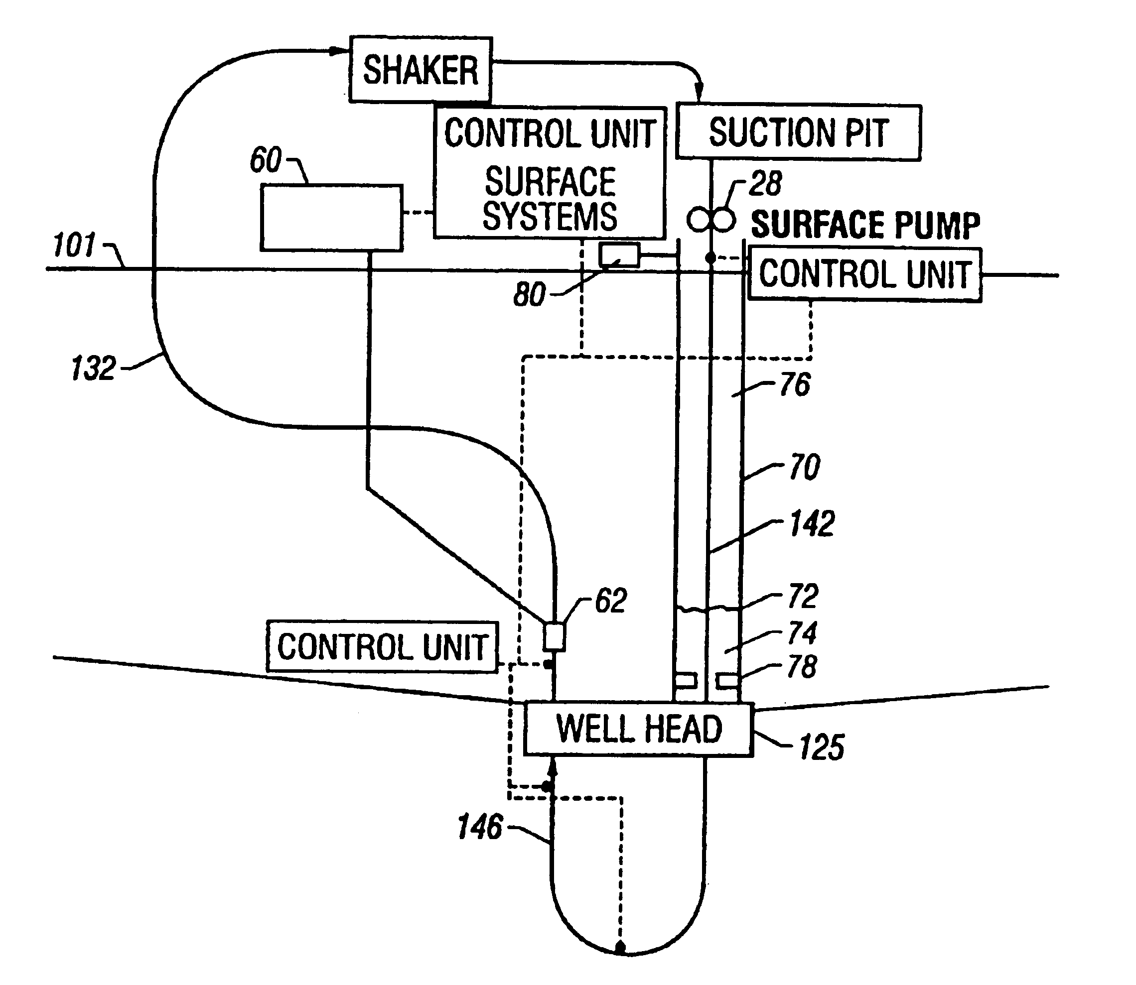
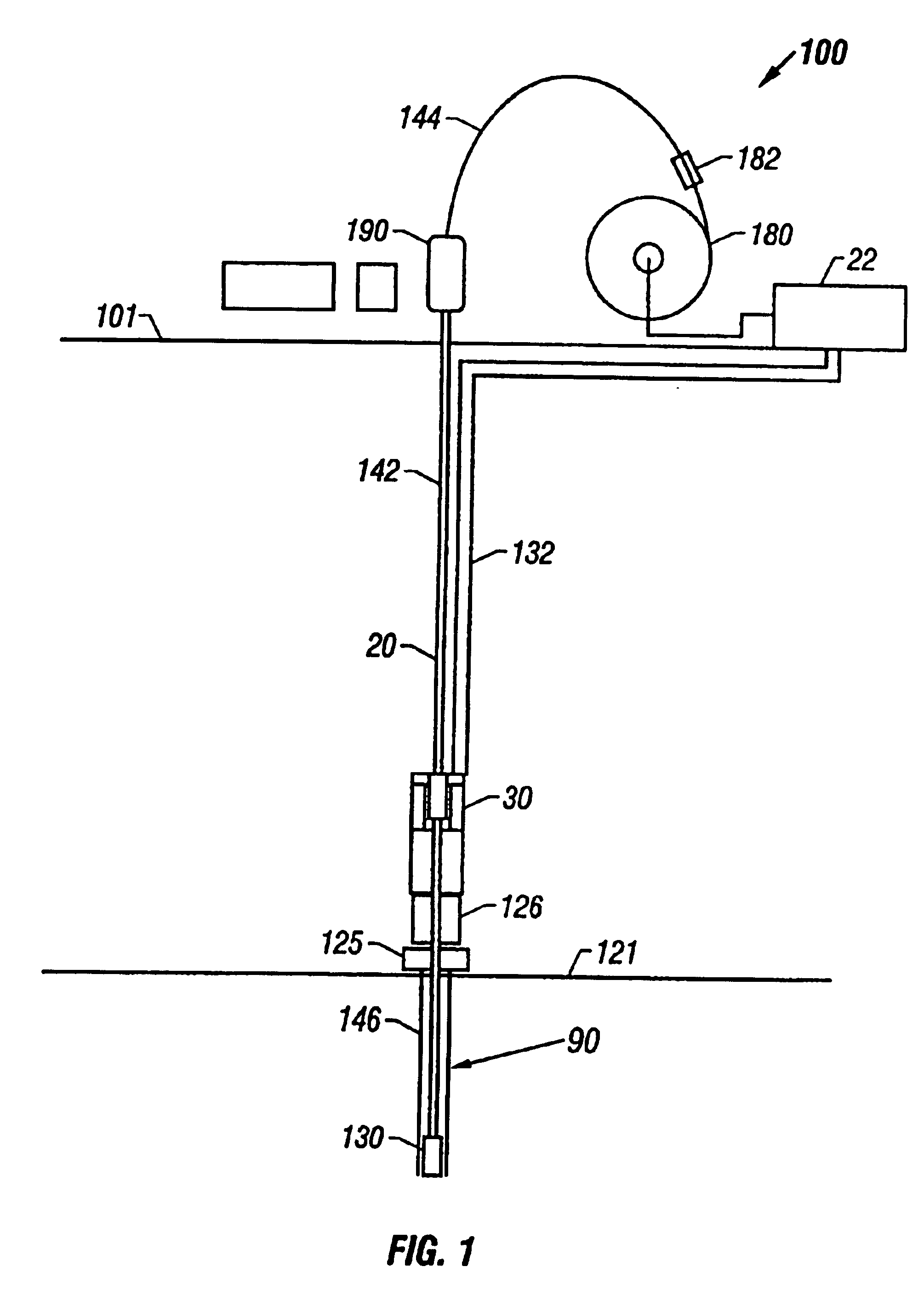
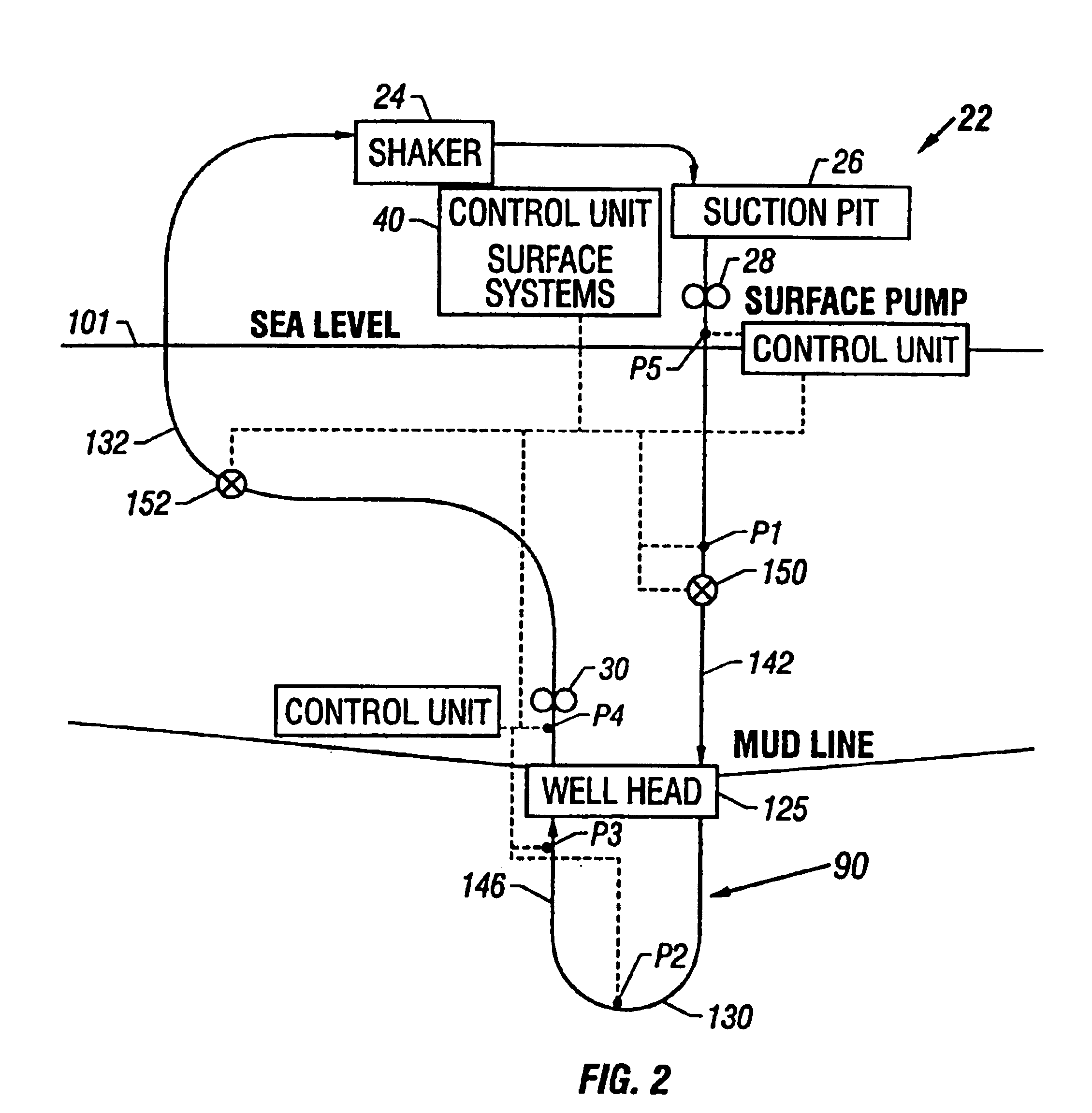
FIG. 1 shows a schematic elevational view of a drilling system 100 for drilling subsea or under water wellbores 90. The drilling system 100 includes a drilling platform, which may be a drill ship 101 or another suitable surface work station such as a floating platform or a semi-submersible. Various types of work stations are used in the industry for drilling or performing other wellbore operations in subsea wells. A drilling ship or a floating rig is usually preferred for drilling deep water wellbores, such as wellbores drilled under several thousand feet of water. To drill a wellbore 90 under water, wellhead equipment 125 is deployed above the wellbore 90 at the sea bed or bottom 121. The wellhead equipment 125 includes a blow-out-preventer stack 126. A lubricator (not shown) with its associated flow control valves may be provided over the blow-out-preventer 126. The flow control valves associated with the lubricator control the discharge of the returning drilling fluid from the lu...


PUM


Abstract

The present invention provides drilling systems for drilling subsea wellbores. The drilling system includes a tubing that passes through a sea bottom wellhead and carries a drill bit. A drilling fluid system continuously supplies drilling fluid into the tubing, which discharges at the drill bit bottom and returns to the wellhead through an annulus between the tubing and the wellbore carrying the drill cuttings. A fluid return line extending from the wellhead equipment to the drilling vessel transports the returning fluid to the surface. In a riserless arrangement, the return fluid line is separate and spaced apart from the tubing. In a system using a riser, the return fluid line may be the riser or a separate line carried by the riser. The tubing may be coiled tubing with a drilling motor in the bottom hole assembly driving the drill bit. A suction pump coupled to the annulus is used to control the bottom hole pressure during drilling operations, making it possible to use heavier drilling muds and drill to greater depths than would be possible without the suction pump. An optional delivery system continuously injects a flowable material, whose fluid density is less than the density of the drilling fluid, into the returning fluid at one or more suitable locations the rate of such lighter material can be controlled to provide supplementary regulation of the pressure. Various pressure, temperature, flow rate and kick sensors included in the drilling system provide signals to a controller that controls the suction pump, the surface mud pump, a number of flow control devices, and the optional delivery system.

Description

BACKGROUND OF THE INVENTION1. Field of the InventionThis invention relates generally to oilfield wellbore systems for performing wellbore operations and more particularly to subsea downhole operations at an offshore location in which drilling fluid is continuously circulated through the wellbore and which utilizes a fluid return line that extends from subsea wellhead equipment to the surface for returning the wellbore fluid from the wellhead to the surface. Maintenance of the fluid pressure in the wellbore during drilling operations at predetermined pressures is key to enhancing the drilling operations.2. Background of the ArtOilfield wellbores are drilled by rotating a drill bit conveyed into the wellbore by a drill string. The drill string includes a drilling assembly (also referred to as the “bottom hole assembly” or “BHA”) that carries the drill bit. The BHA is conveyed into the wellbore by tubing. Continuous tubing such as coiled tubing or jointed tubing is utilized to convey t...

Claims


Application Information

Patent Timeline
IPC IPC(8): E21B17/00E21B19/22E21B17/20E21B7/28E21B7/00E21B19/00E21B33/03E21B21/00E21B7/12E21B7/128E21B19/09E21B33/076E21B43/12B63B21/50E21B21/08
CPCB63B21/502E21B7/128E21B7/28E21B17/206E21B19/002E21B19/09E21B19/22E21B21/00E21B21/001E21B21/08E21B33/076E21B43/121E21B43/122E21B7/002E21B2021/006E21B21/085E21B7/12
Inventor FINCHER, ROGER W.MAY, ROLANDFONTANA, PETERWATKINS, LARRYMACFARLANE, JAMES W.
Owner BAKER HUGHES INC
Why Eureka
Try Eureka