Coating film layer moisture adjusting device and planographic printing plate producing method

Inactive Publication Date: 2005-02-15
FUJIFILM HLDG CORP +1
View PDF5 Cites 4 Cited by
  • Summary
  • Abstract
  • Description
  • Claims
  • Application Information

AI Technical Summary

Benefits of technology

According to the second aspect of the present invention, the moisture content contained in the overcoat layer formed on the surface of the photosensitive layer or the heat-sensitive layer can be maintained with high precision or adjusted over time to a target moisture content set in advance in accor

Problems solved by technology

A large moisture content may lead to an increase in sensitivity, and thus fogging problems may easily occur.
On the other hand, a small moisture content may lead to a decrease in sensitivity.
Accordingly, the planographic printing plate has a problem in that the quality thereof becomes unstable when the moisture content of the overcoat layer is not within an appropriate range.
As a result, the moisture conte

Method used


Image

  • Coating film layer moisture adjusting device and planographic printing plate producing method
  • Coating film layer moisture adjusting device and planographic printing plate producing method
  • Coating film layer moisture adjusting device and planographic printing plate producing method

Examples


first embodiment

(First Embodiment)

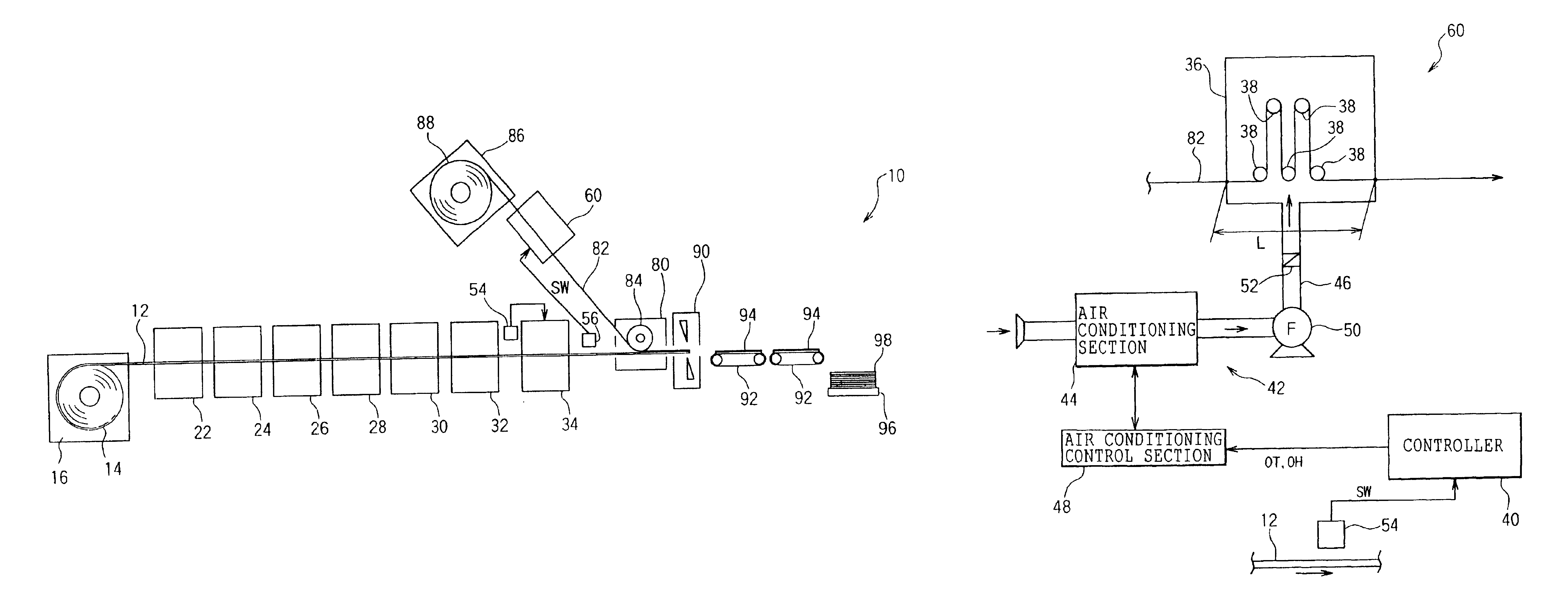
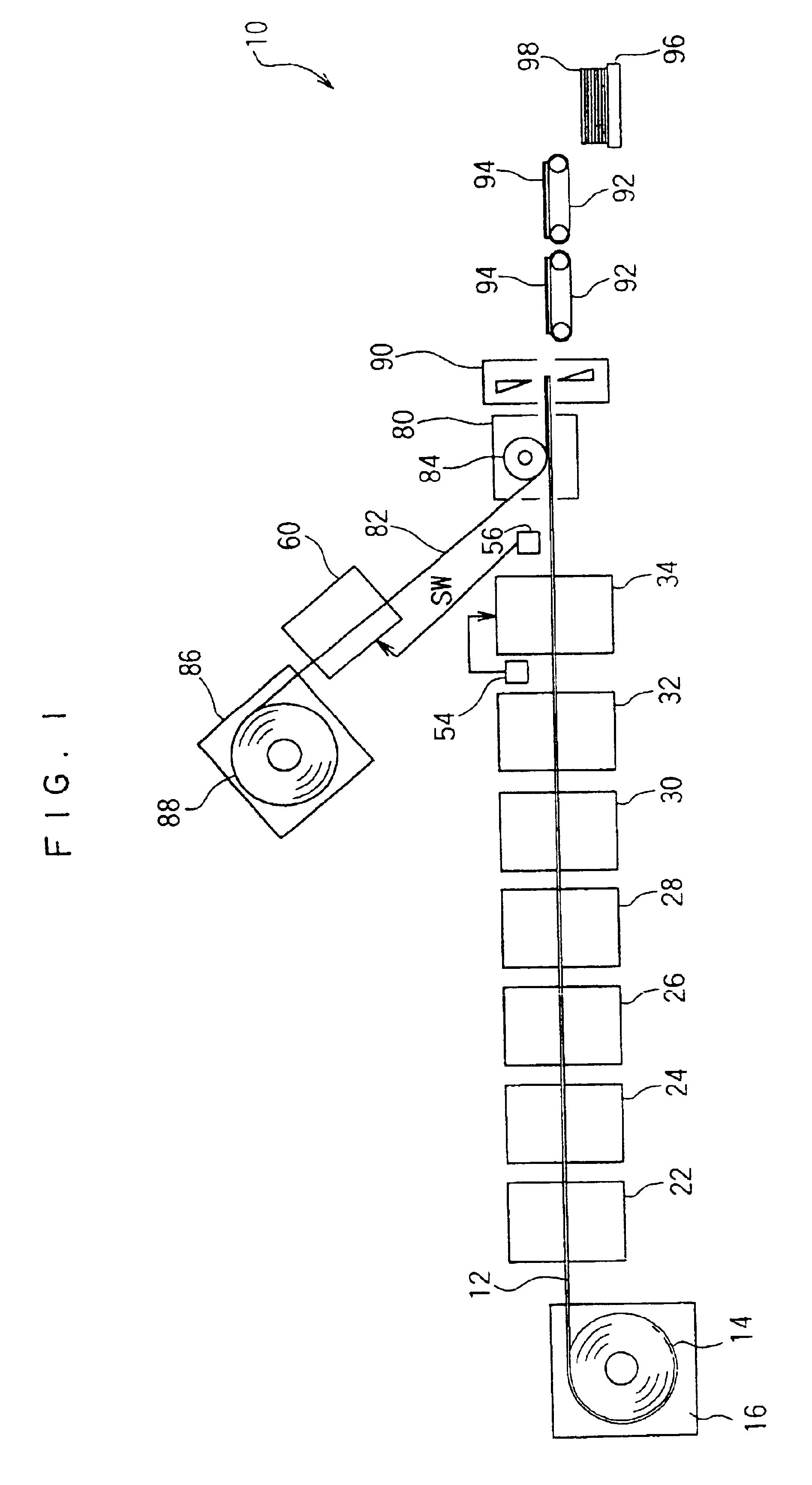
FIG. 1 shows a producing line for planographic printing plate according to a first embodiment of the invention. A feeding device 16 is disposed at a most upstream side (the left side in FIG. 1) of the producing line 10. An aluminum coil 14 on which an aluminum web 12 with a thickness of, e.g., 0.1 to 0.5 mm is taken up in a roll is loaded within the feeding device 16. The feeding device 16 feeds the aluminum web 12 toward a downstream side at a speed corresponding to a producing speed of the entire producing line 10 (i.e., a line speed). The aluminum web 12 serving as a support for planographic printing plate may be made of, e.g., JIS 1050 material, JIS 1100 material, JIS 1070 material, Al—Mg-based alloy, Al—Mn-based alloy, Al—Mn—Mg-based alloy, Al—Zr-based alloy and Al—Mg—Si-based alloy or the like.

A mechanical or electrochemical roughening device 22 is disposed at a downstream side of the feeding device 16 in the producing line 10. The roughening device 22 perfor...

second embodiment

(Second Embodiment)

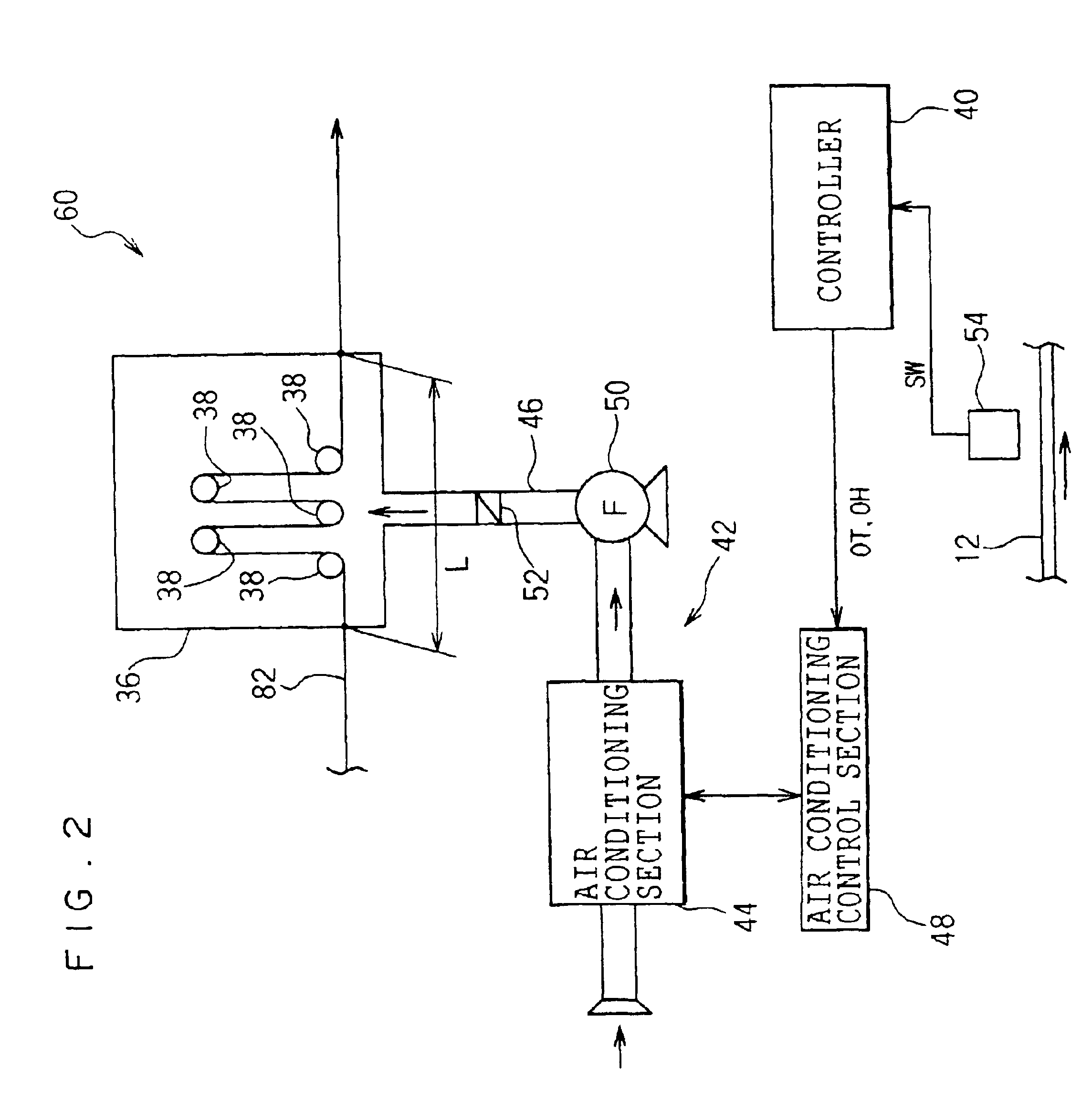
FIG. 3 shows a moisture adjusting device 62 according to a second embodiment of the invention. The moisture adjusting device 62 is applied to the producing line 10, in place of the secondary moisture adjusting device 60 according to the first embodiment. Members for the moisture adjusting device 62 according to the second embodiment that have common structure and operation to those of the secondary moisture adjusting device 60 according to the first embodiment are denoted by the same reference numerals, and descriptions thereof will be omitted.

The secondary moisture adjusting device 62 shown in FIG. 3 is different from the secondary moisture adjusting device 60 shown in FIG. 2 in that a pass length adjusting mechanism 64 for adjusting a pass length of the interposing paper web 82 within the humidity conditioning tank 36 is provided, and a function of controlling the pass length adjusting mechanism 64 is added to a controller 78. The pass length L adjusted by the p...


PUM


Abstract

A controller for a moisture adjusting device of the present invention reads out a target moisture content set in advance in a data table in accordance with a type of a planographic printing plate; determines, every predetermined control period, a moisture content of an overcoat layer (measured moisture content) based on a measured signal SW; and calculates a difference (deviation) between the measured moisture content and the target moisture content. For example, if the measured moisture content of the overcoat layer is lower than the target moisture content, the controller sets an adjusted moisture content which is higher than the measured moisture content and controls the humidity and the temperature within a humidity conditioning zone so that an interposing paper web (protective sheet material) attains the adjusted moisture content within the humidity conditioning zone.

Description

CROSS-REFERENCE TO RELATED APPLICATIONThis application claims priority under 35 USC 119 from Japanese patent application, No. 2002-241620, the disclosure of which is incorporated by reference herein.BACKGROUND OF THE INVENTION1. Field of the InventionThe present invention relates to a moisture adjusting device for adjusting a moisture content contained in a coating film layer formed by applying a coating solution containing an organic solvent, water and the like onto a support, and a planographic printing plate producing method that uses the moisture adjusting device.2. Description of the Related ArtIn recent years, along with development in digital processing techniques for image processing, a photopolymer which is formed so as to have high sensitivity to laser beam in a visible range by using photo-radical polymerization, is often used as a photosensitive material for planographic printing plate in order to implement a direct plate-making system. In the planographic printing plate...

Claims


Application Information

Patent Timeline
IPC IPC(8): B41C1/10G03C1/74G03F7/11B41N3/00G03F7/38
CPCB41C1/10G03C1/74B41M2205/12
Inventor MINATO, SHINICHIRO
Owner FUJIFILM HLDG CORP
Why Eureka
Try Eureka