Thin brushless motor having resin-insulated concentric ring-shaped bus bars

a brushless motor and concentric ring technology, applied in the direction of windings, engine-driven generators, magnetic circuit shapes/forms/construction, etc., can solve the problems of inability to obtain high-dimensional accuracy products, inability to hold predetermined gaps, and difficulty in achieving heat resistance and mechanical strength. , to achieve the effect of further improving dielectric resistance and heat resistan

Inactive Publication Date: 2005-02-15
SUMITOMO WIRING SYST LTD +1
View PDF38 Cites 39 Cited by
  • Summary
  • Abstract
  • Description
  • Claims
  • Application Information

AI Technical Summary

Benefits of technology

When the material for forming the insulating holder is PPS, the heat resistance and the mechanical strength can be improved. Furthermor

Problems solved by technology

Therefore, relative positions of the bus bars are often varied, and a situation in which the predetermined gap cannot be held may occur.
This problem is very noticeable in such bus bars of a substantially annular shape.
Consequently, there is a possibility that a product of high dimensional accuracy cannot be obtained.
In suc

Method used


Image

  • Thin brushless motor having resin-insulated concentric ring-shaped bus bars
  • Thin brushless motor having resin-insulated concentric ring-shaped bus bars
  • Thin brushless motor having resin-insulated concentric ring-shaped bus bars

Examples


second embodiment

(Second embodiment)

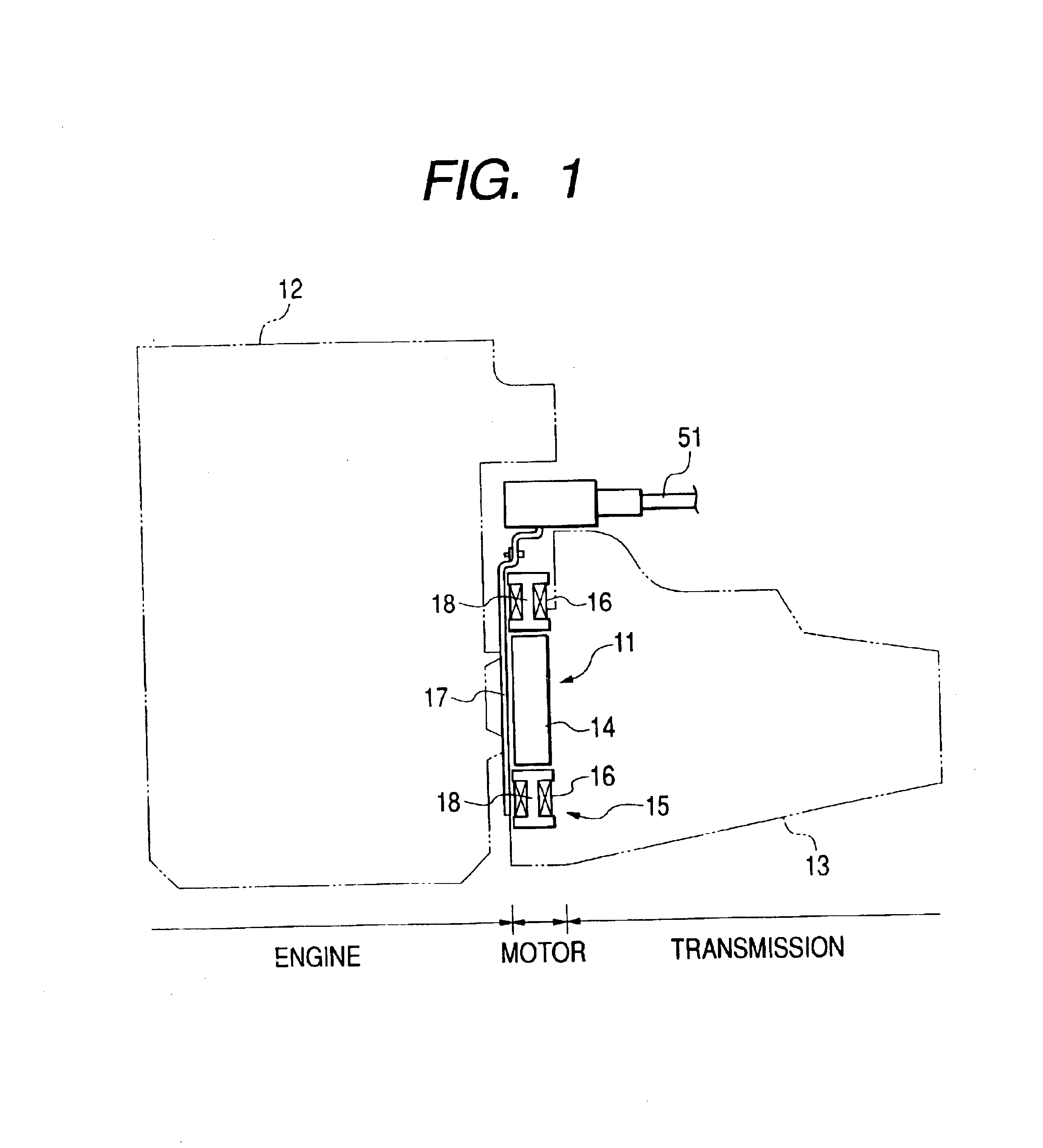
Next, a second embodiment will be described. In this embodiment, only parts which are different from those of the above embodiment will be described.

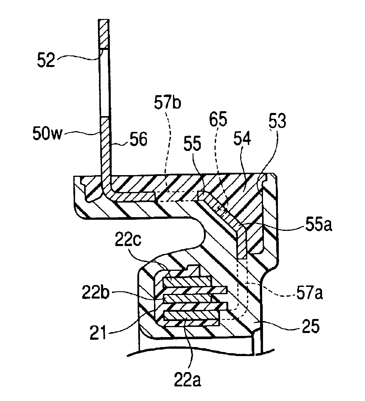
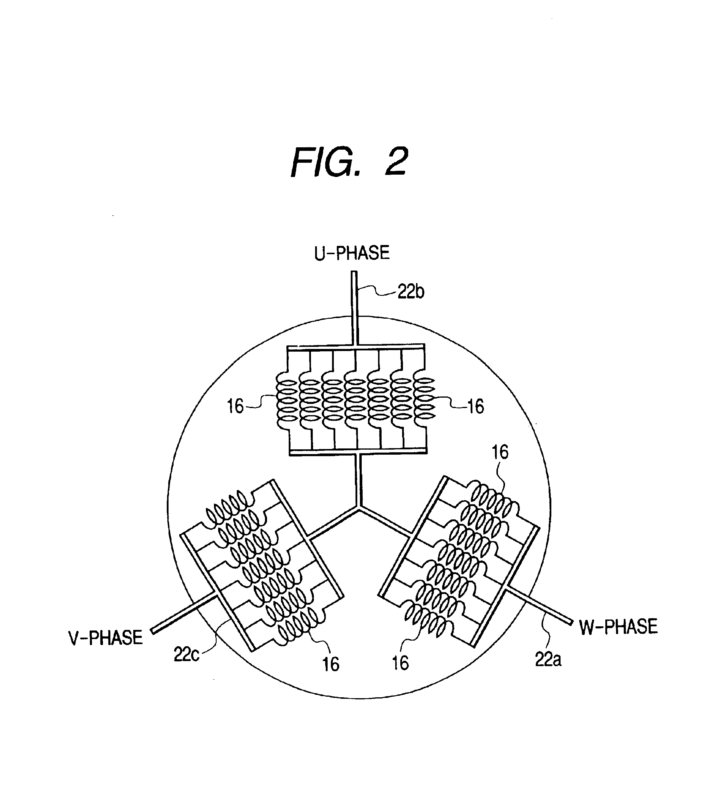
In the above embodiment, the insulating holder 21 is configured by a single member. In contrast, in this embodiment, as shown in FIGS. 33 and 34, the insulating holder 21 is configured by a plurality of arcuate resin molded products 95. In the same manner as the configuration of the insulating holder 21, the holding grooves 23a to 23c which are defined by the walls 43a to 43d are formed in each of the arcuate resin molded products 95. The arcuate resin molded products 95 are arranged along the circumferential direction of the bus bars 22a, 22b, and 22c so that both ends of each of the molded products 95 are joined to the end faces of adjacent arcuate resin molded products 95, respectively. As a result, the insulating holder 21 is formed into a continuous annular shape.

When insert molding is to be conducted, the bus ba...


PUM


Abstract

A centralized power distribution unit for a vehicular thin brushless motor includes a plurality of bus bars, a resin insulation layer that covers the bus bars, and an insulating holder having a plurality of holding grooves that hold the bus bars. The bus bars are pre-bent in a thickness direction to be formed into a substantially annular shape. Each of the bus bars is provided correspondingly with a phase of the motor. The holding grooves are formed in parallel extending along a circumferential direction of the centralized power distribution unit. The bus bars are respectively inserted into the holding grooves, and are thus stacked in a radial direction of the centralized power distribution unit. The insulating holder and the bus bars are covered by the resin insulation layer.

Description

BACKGROUND OF THE INVENTION1. Field of InventionThe present invention relates to a centralized power distribution unit for a vehicular thin brushless motor.2. Description of Related ArtRecently, automobiles with good fuel economy have been in high demand. As one example of automobile manufacturers' efforts to meet these demands, hybrid cars with super low fuel consumption have been developed. In particular, a hybrid car has been proposed recently which is provided with an auxiliary power mechanism (a motor assist mechanism) in which an engine provides the main power and a DC brushless motor assists the engine upon acceleration or the like.The motor assist mechanism is subject to much constraint in installation, since a brushless motor constituting the motor assist mechanism is disposed in a limited space, for example, a space between an engine and a transmission in an engine compartment. Thus, such a brushless motor is required to have a thin configuration.A thin brushless motor to ...

Claims


Application Information

Patent Timeline
IPC IPC(8): H02K3/52H02K3/46H02K15/00H02K7/00B60L50/10B60L50/16H02K5/22
CPCH02K3/522H02K15/0062H02K15/0056H02K7/006H02K2203/09
Inventor KOBAYASHI, MAKOTOSUZUKI, IZUMIHORIE, TATSUROFUKUDA, KENJITAKEUCHI, KAZUO
Owner SUMITOMO WIRING SYST LTD
Why Eureka
Try Eureka