Power cable
a power cable and cable technology, applied in the direction of power cables, cables, insulated conductors, etc., can solve the problems of poor thermal stability, poor strippability, and the typical insulation shield does not have the optimal strippability, and achieve satisfactory thermal stability and improved strippability.
- Summary
- Abstract
- Description
- Claims
- Application Information
AI Technical Summary
Benefits of technology
Problems solved by technology
Method used
Image
Examples
examples 1 to 10
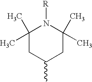
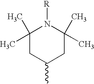
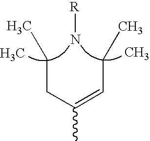
Examples 1 and 2 demonstrate the effect of including a TMP in tree resistant, crosslinked insulation having an ethylene / ethyl acrylate copolymer insulation shield over the insulation. In this case, the ethyl acrylate content is 35 percent by weight of the polymer. Without a TMP in the insulation (example 1), the insulation shield is fully bonded to the insulation, and cannot be stripped. With a TMP (example 2), the strip force is 10 pounds per 0.5 inch, which is within the typical range for commercial cables.
Strip force is reported in pounds per 0.5 inch. It is measured as follows:
Single plaques are prepared from insulation shield formulation pellets and insulation layer formulation pellets by compression molding. Prior to compression molding, the pellets are melted on a two roll-mill. An organic peroxide is added if crosslinking is desired. The temperature for compression molding of shield pellets is 110 degrees C. Approximately 65 grams of shield formulation are used to prepare a ...
examples 3 and 4
demonstrate the effect of including a TMP in tree resistant, crosslinked insulation having an ethylene / vinyl acetate copolymer insulation shield over the insulation. In this case, the vinyl acetate content is 28 percent by weight of the polymer. Without a TMP in the insulation (example 3), the strip force is 13 pounds per 0.5 inch. With a TMP (example 4), the strip force is 8 pounds per 0.5 inch, a 38 percent reduction in strip force.
examples 5 through 10
demonstrate the effect of including a TMP in tree resistant, crosslinked insulation having an ethylene / vinyl acetate copolymer insulation shield over the insulation. In this case, the vinyl acetate content is 32 percent by weight of the polymer. The insulation shield also contains various levels of NBR. With no NBR, the reduction in strip force with a TMP containing insulation (example 6) relative to a similar insulation without a TMP (example 5) is insignificant (10 pounds per 0.5 inch versus 11 pounds per 0.5 inch, i.e., a 9 percent reduction). With 5 percent by weight NBR, the reduction with a TMP containing insulation (example 8) relative to a similar insulation without a TMP (example 7) is a significant 36 percent. With 10 percent by weight NBR, the reduction with a TMP containing insulation (example 10) relative to a similar insulation without a TMP (example 9) is a significant 71 percent.
PUM
| Property | Measurement | Unit |
|---|---|---|
| Percent by mass | aaaaa | aaaaa |
| Percent by mass | aaaaa | aaaaa |
| Percent by mass | aaaaa | aaaaa |
Abstract
Description
Claims
Application Information
 - R&D
- Intellectual Property
- Life Sciences
- Materials
- Tech Scout
- Unparalleled Data Quality
- Higher Quality Content
- 60% Fewer Hallucinations
Browse by: Latest US Patents, China's latest patents, Technical Efficacy Thesaurus, Application Domain, Technology Topic, Popular Technical Reports.
© 2025 PatSnap. All rights reserved.Legal|Privacy policy|Modern Slavery Act Transparency Statement|Sitemap|About US| Contact US: help@patsnap.com


