Ergonomic multi-unit test fixture

Inactive Publication Date: 2005-02-22
ADTRAN
View PDF3 Cites 20 Cited by
  • Summary
  • Abstract
  • Description
  • Claims
  • Application Information

AI Technical Summary

Benefits of technology

In accordance with the present invention shortcomings of conventional test connection arrangements, such as those referenced above, are effectively obviated by a multi-module test fixture configuration that facilitates reliable ergonomic connectivity with a test apparatus of a plurality of communication units, which may be of the same or different sizes, in a space efficient and ease of access architecture. As will be described, the multi-module test fixture of the invention requires only minimal physical effort on the part of test personnel to insert a unit under test and to make connections thereto.
To this end the multi-module test fixture of the invention comprises a multi-shelf unit that is installable in a standard electronic equipment rack that houses various test equipments to which a plurality of units under test (UUTs) are to be connected for testing. To facilitate insertion and connection of various units under test onto the shelves, the multi-shelf unit is preferably mounted in the rack at a height corresponding to the waist and eyes of a test equipment operator. A respective multi-shelf unit contains a plurality of vertically spaced apart shelves, a respective one of which has a generally ‘flattened-U’ shaped channel configuration including an upper, module-support plate, and an input/output connector plate. The top surface of the module-support plate is preferably coated with a low-friction material, to facilitate operator insertion and removal of a unit under test and to protect the UUT from cosmetic damage.
The input/output connector plate has a plurality of apertures that are configured to receive various types and shapes

Problems solved by technology

While such test fixtures may be satisfactory for relatively small components, they cannot be used for relatively large‘box-configured’ devices, such as stand-alone communication modules containing one or more circuit boards housed within a common enclosure that is intended to be used as a tabletop or shelf-supported product.
Each of these approaches has inherent drawbacks.
The first

Method used


Image

  • Ergonomic multi-unit test fixture
  • Ergonomic multi-unit test fixture
  • Ergonomic multi-unit test fixture

Examples


Embodiment Construction

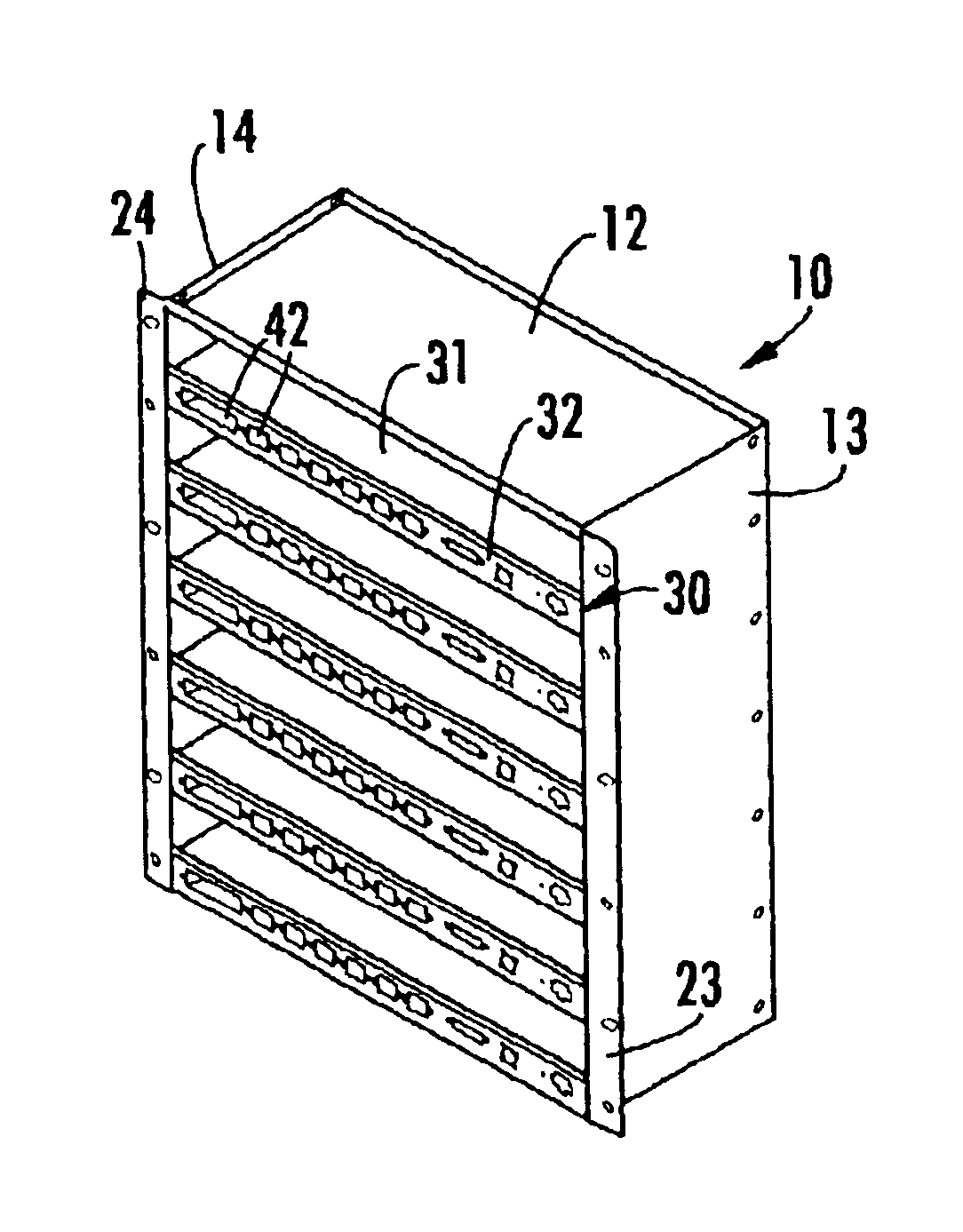
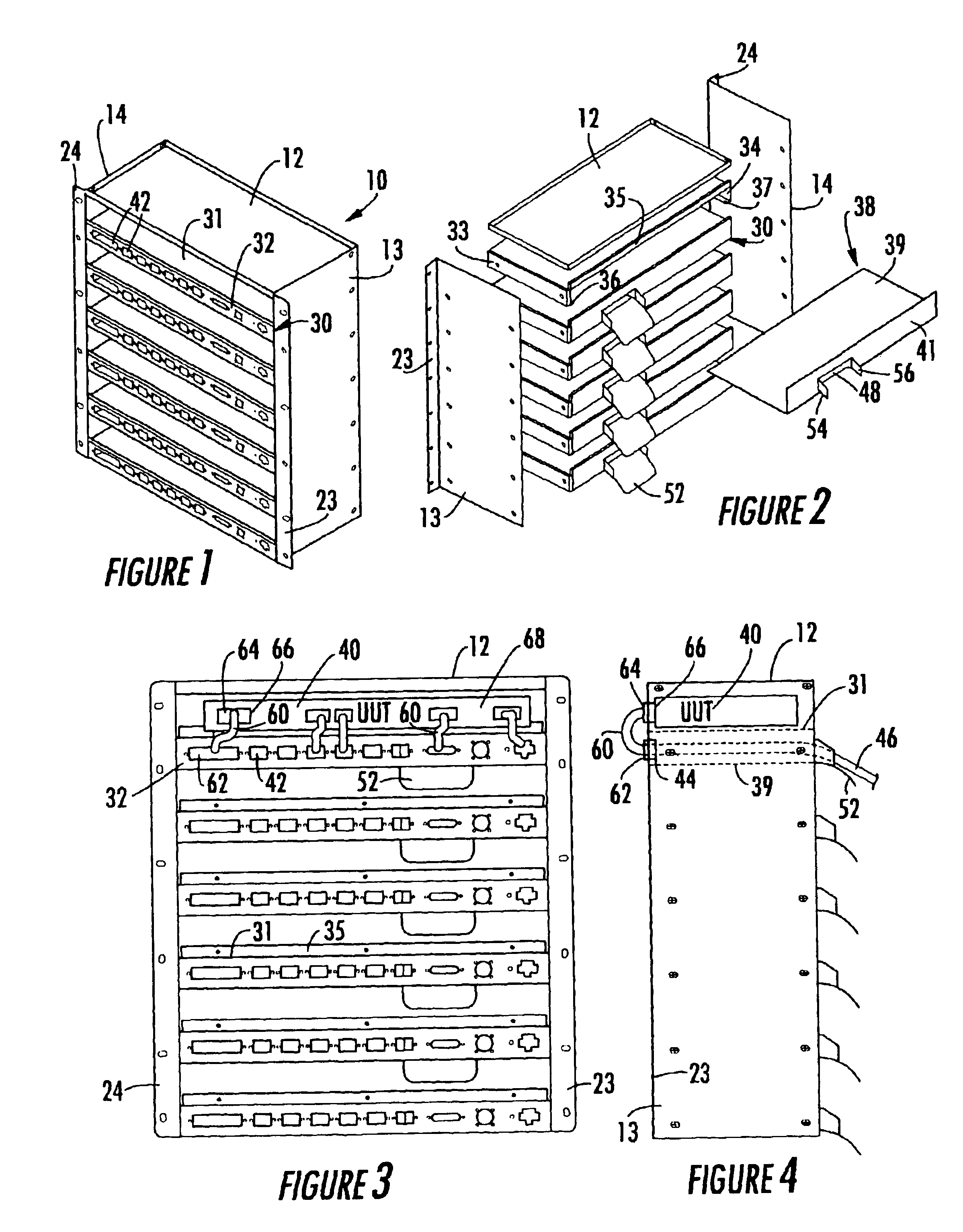
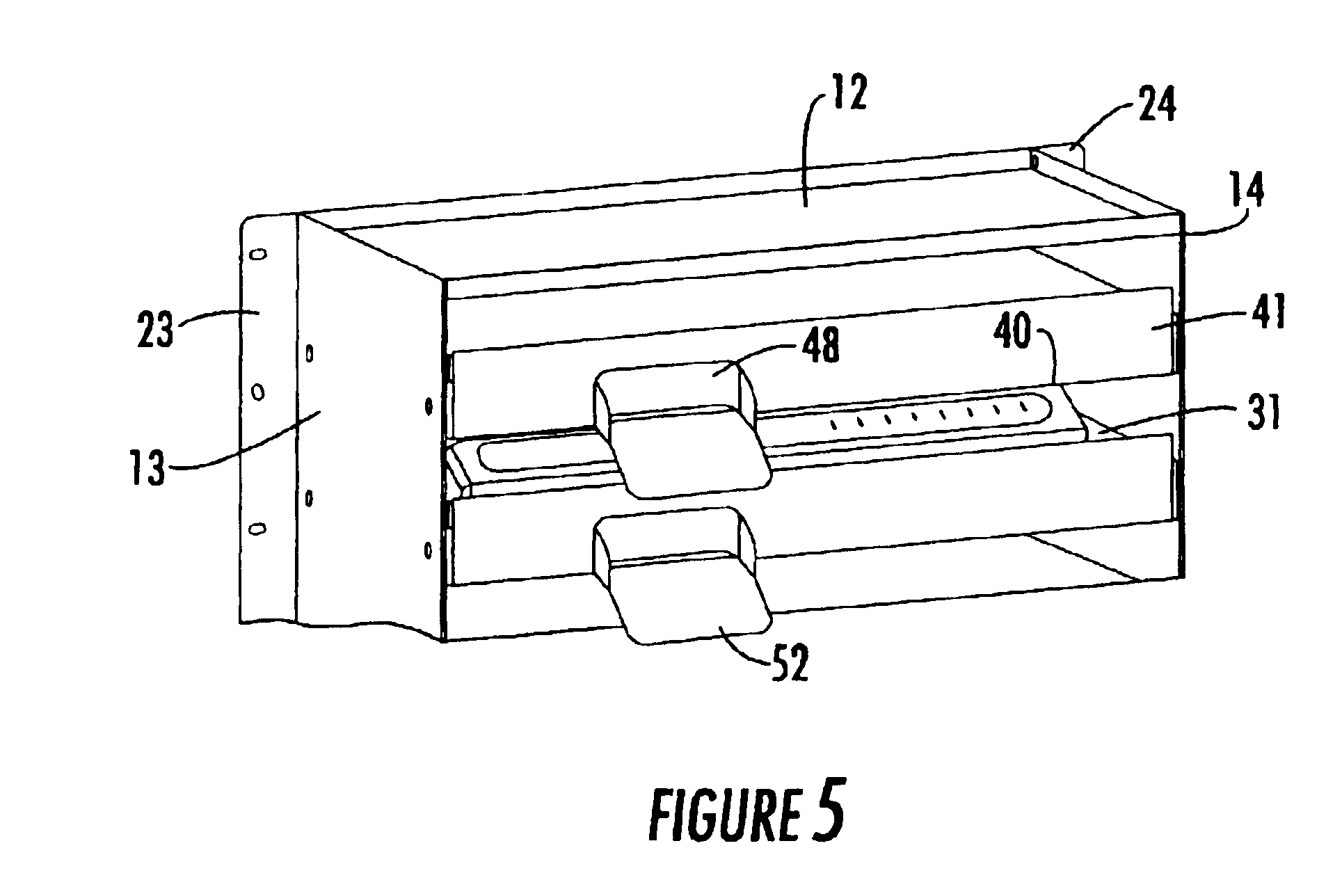
Attention is now directed to FIGS. 1-6, wherein the multi-module test fixture of the invention is diagrammatically shown as comprising a multi-shelf unit 10 that is configured to be installed within an industry standard floor-mounted equipment rack 20. The equipment rack 20 also houses various test equipments to which a plurality of electronic (e.g., telecommunication) units under test (UUTs) are to be connected for testing. As a non-limiting example, multi-shelf unit 10 is shown as containing six, vertically spaced apart shelves 30-1, . . . , 30-6, so as to form associated UUT test cavities therebetween. It is to be understood, however, that the invention is not limited to this or any particular number. To facilitate access by test personnel, the multi-shelf unit 10 is preferably mounted at a height corresponding to the vicinity of the waist and eyes of a test equipment operator, so as to facilitate the operator's insertion and connection of various communication modules or units u...


PUM


Abstract

A test fixture interfaces plural units under test (UUTs) with test equipment within a common equipment rack. The test fixture supports a plurality of vertically spaced apart shelf units. A shelf unit has a support surface and an input/output connector panel adjacent thereto, that define a UUT insertion cavity. An input/output connector panel contains cable terminations that terminate cables to various testing equipments. Insertion of a UUT into the insertion cavity places communication ports of the UUT adjacent to cable terminations of the adjacent input/output connector panel. Jumper cables interconnect communication ports of the UUT with cable terminations of the adjacent input/output connector panel.

Description

FIELD OF THE INVENTIONThe present invention relates in general to electronic test systems and subsystems, and is particularly directed to a new and improved multi-unit or test fixture configuration that facilitates ergonomic interconnectivity of a plurality of electronic modules or units, such as telecommunication modules, with a test apparatus therefor, in a space efficient and ease of access architecture.BACKGROUND OF THE INVENTIONTraditional fixtures for testing a plurality of electronic circuit modules include ‘card cage’ structures, in which units (e.g., circuit boards) under test are ‘plugged’ into a backplane, and ‘bed of nails’ methods that connect probe points of the test fixture with the tested components. While such test fixtures may be satisfactory for relatively small components, they cannot be used for relatively large‘box-configured’ devices, such as stand-alone communication modules containing one or more circuit boards housed within a common enclosure that is intend...

Claims


Application Information

Patent Timeline
IPC IPC(8): H05K7/14G01R31/28H04Q1/06
CPCG01R31/2808H04Q1/06H04Q1/20H05K7/1448H04Q2201/02
Inventor EWING, PHILLIP H.ROTH, MARC L.WOOTEN, PAUL L.
Owner ADTRAN
Why Eureka
Try Eureka