
Display unit and mobile apparatus using the unit

a display unit and mobile device technology, applied in the field of display units, can solve the problems of poor heat resistance of the display device to be assembled into the display unit, heat generation during the charging/discharging operation, and is generally considered to be difficult to combine the display device with the secondary battery, so as to reduce the size, weight and thickness of the entire unit and achieve good displaying function.

Inactive Publication Date: 2005-02-22
KK TOSHIBA
View PDF11 Cites 22 Cited by
  • Summary
  • Abstract
  • Description
  • Claims
  • Application Information

AI Technical Summary

Benefits of technology

The present invention had been achieved for solving the aforementioned problems. Accordingly, a main object of the present invention is to provide a display unit and a mobile apparatus in which heat conduction from the secondary battery is shut off, and the display unit and the secondary battery are integrally formed so as to reduce a size, weight and thickness of an entire unit, and capable of maintaining a good displaying function for a long period of time.
Another object of the present invention is to provide a display unit in which the display unit and the secondary battery are integrally formed and the heat conduction from the secondary battery is shut off thereby to positively cool the secondary battery so as to maintain and improve the function of the display unit and to reduce the size, weight and thickness of the display unit.
Further object of the present invention is to provide a display unit and a mobile apparatus in which a heat shielding layer is disposed between the display unit and the secondary battery to increase mechanical strength and physical strength of the display unit as a structural body.
Still further object of the present invention is to provide a display unit and a mobile apparatus in which the secondary battery is provided with a shock-absorbing function so as to impart a high impact resistance to the unit and apparatus even if the size, weight and thickness of the unit or the apparatus are reduced.
Further, an additional object of the present invention is to provide a display unit in which the display unit and the secondary battery are integrally formed, so that the mobile apparatus can be made to be compact so as to reduce the weight thereof.

Problems solved by technology

On the other hand, it has been known that the display device to be assembled into the display unit has a weak resistance to heat or stress due to display materials such as liquid crystal or the like and structural factors of the display device.
In addition, the secondary battery assembled into the mobile apparatus causes a heat generation during the charging / discharging operations.
In this regard, it has been generally considered to be difficult to combine the display device with the secondary battery so as to integrate each other for the purpose of making the mobile apparatus compact to obtain a light weight i.e., for the purpose of making the display device compact and thin to provide light weight.
In actual, the display device such as liquid crystal cell or the like is weak against heat or stress, and the function of the liquid crystal material is greatly lowered by the heat generated during the charging / discharging operation of the secondary battery, so that there has been posed a problem that the displaying function of the display device is damaged and lost.

Method used


Image

  • Display unit and mobile apparatus using the unit
  • Display unit and mobile apparatus using the unit
  • Display unit and mobile apparatus using the unit

Examples


fourth embodiment

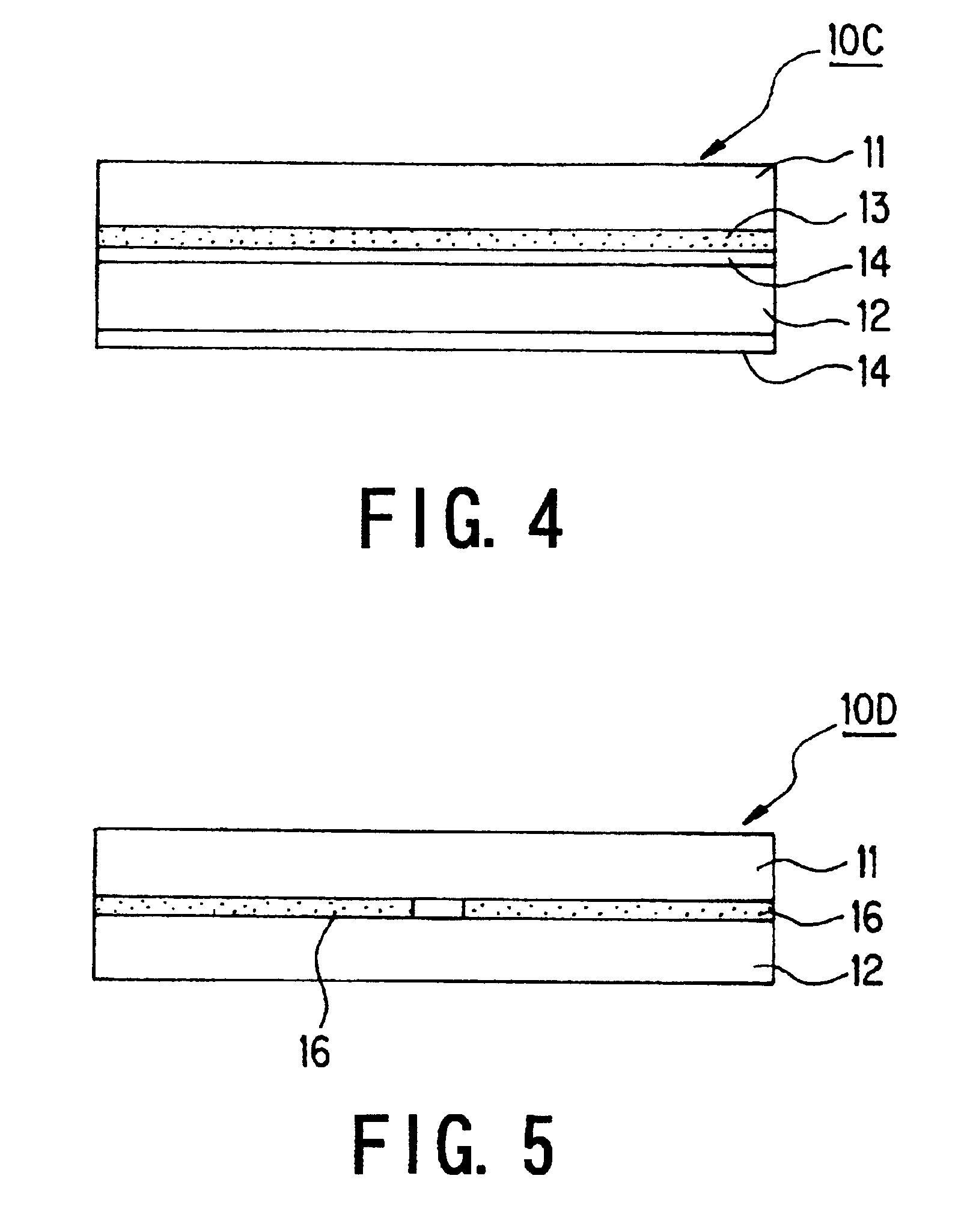
FIG. 4 is a basic principle view showing a display unit according to the present invention.

This display unit 10C shown in FIG. 4 is constituted by integrally providing a heat radiating plate 14 or a cooling plate to the rear side of the display unit 10B shown in FIG.3.

In this display unit 10C, the heat generated from the secondary battery 12 is positively discharged by the heat radiating plate 14, or absorbed by the cooling plate provided to both surfaces of the secondary battery, so that it becomes possible to effectively and positively prevent the adverse influences of the heat generation caused by the secondary battery 12 from exerting on a side of the display device 11.

fifth embodiment

FIG. 5 is a basic principle view showing a display unit according to the present invention.

The display unit 10D shown in FIG. 5 is constituted by comprising: a plate-shaped display device 11 as an array substrate or a liquid crystal cell; thin-type secondary battery 12 as a power source; and double-coated adhesive tapes 16, 16, where in the display device 11 and the secondary battery 12 are integrally combined and fixed through the double-coated adhesive tapes. The double-coated adhesive tapes 16, 16 are formed of synthetic resin material having a thermal conductivity of at most 1 W / mK, and form heat shielding sheets as heat shielding layers. The thickness of the double-coated adhesive tapes 16, 16 is set to about 100 μm to about 1 mm, preferably to 100 μm to 200 μm.

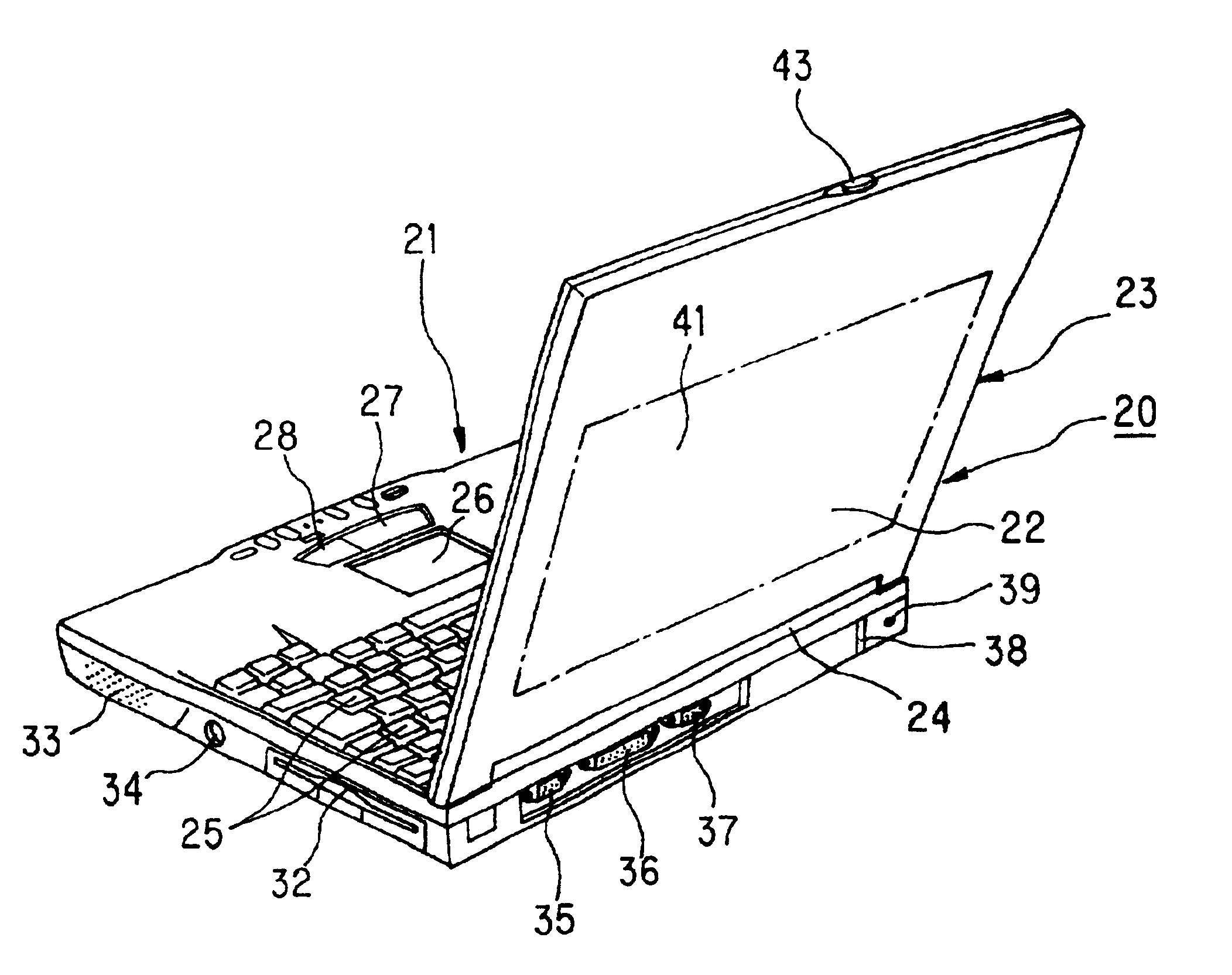
Next, concrete embodiments of the display unit according to the present invention will be explained hereunder with reference to FIG. 6 or after.

FIGS. 6 and 7 show concrete embodiments of notebook-type personal computer (...


PUM

PropertyMeasurementUnit
thicknessaaaaaaaaaa
thicknessaaaaaaaaaa
thicknessaaaaaaaaaa

Abstract

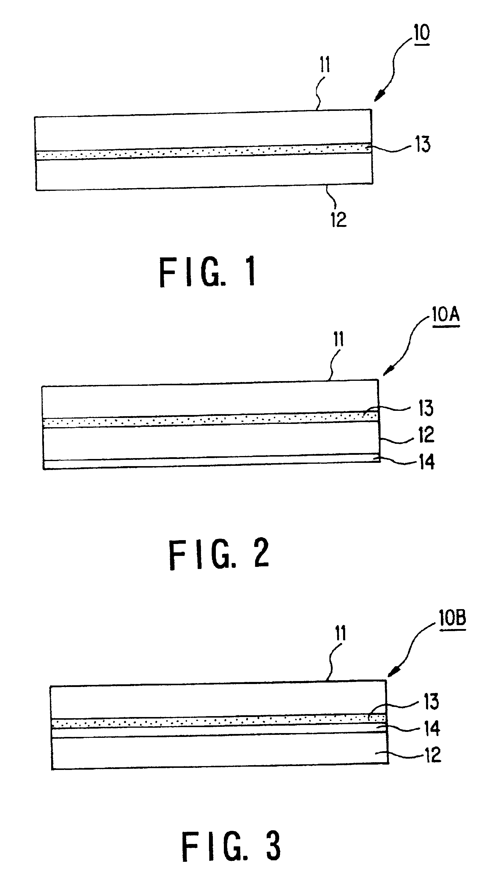
The display unit comprises a display device such as liquid crystal cell or the like; and a secondary battery disposed to a rear side of the display device. A heat shielding layer having a thermal conductivity of at most 5 W / mK, preferably at most 1 W / mK is formed as a heat shielding plate between the display device and the secondary battery, and the display device and the secondary battery are integrally assembled to form a module structure. According to the above structure of the present invention, since the display device such as liquid crystal cell or the like and the secondary battery are integrally assembled to form a module structure, the display unit can be made compact and thin to attain a light weight.

Description

BACKGROUND OF THE INVENTION1. Field of the InventionThe present invention relates to a display unit to be provided for mobile apparatuses such as a portable telephone, a notebook-sized personal computer (PC), a mobile information terminal device or the like, more particularly to a display unit and a mobile apparatus using the display unit, and more particularly to a display unit in which a display device and a thin secondary battery are integrally combined to form a module structure, and to a mobile apparatus into which the display device is assembled.2. Description of the Related ArtAs the mobile apparatuses such as the portable telephone, notebook-sized personal computer (PC) or the like have rapidly become popular, a miniaturization of the mobile apparatuses has been advanced, so that there is a tendency that parts to be assembled are made compact and the parts are replaced by semiconductor elements, while a size of a display device as a liquid crystal cell has been enlarged in v...

Claims


Application Information

Patent Timeline
Patent Type & Authority Patents(United States)
IPC IPC(8): G02F1/133G02F1/13G09F9/00H01M2/10H01M10/05H01M10/0525H01M10/058H04B1/38
CPCG02F1/133308G02F1/133382Y02E60/122H01M2/1066H01M10/052G02F1/133385Y02E60/10Y02P70/50H04B1/38
Inventor KOIWA, KAORUHASEBE, HIROYUKISATOH, ASAKOMOMMA, JUN
Owner KK TOSHIBA
Learn More