
Rapid settling automatic gain control with minimal signal distortion

a gain control and automatic technology, applied in the direction of amplification control, electrical equipment, digital transmission, etc., can solve the problems of inability to achieve the rapid settling time required by an ieee 802.11a lan with an acceptable signal distortion, unfavorable signal to noise ratio loss of detector, unacceptable level of signal distortion, etc., to achieve the effect of high loop gain and rapid settling on

Inactive Publication Date: 2005-02-22
SHARP LAB OF AMERICA INC
View PDF34 Cites 18 Cited by
  • Summary
  • Abstract
  • Description
  • Claims
  • Application Information

AI Technical Summary

Benefits of technology

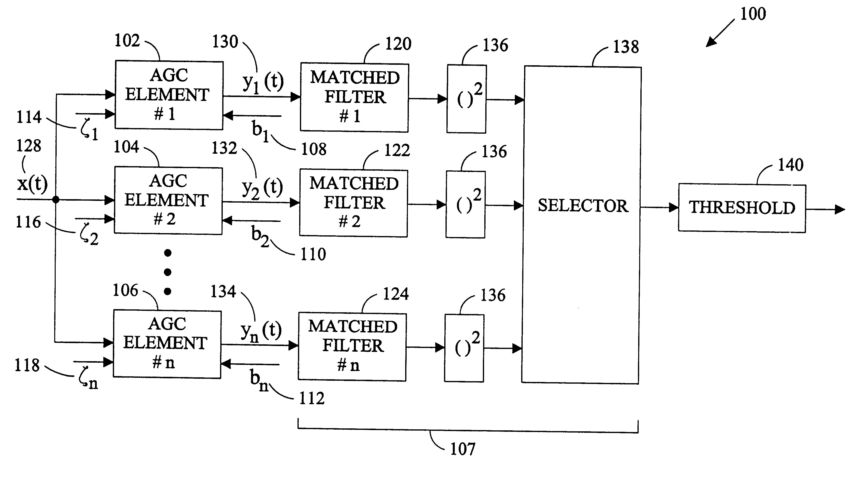
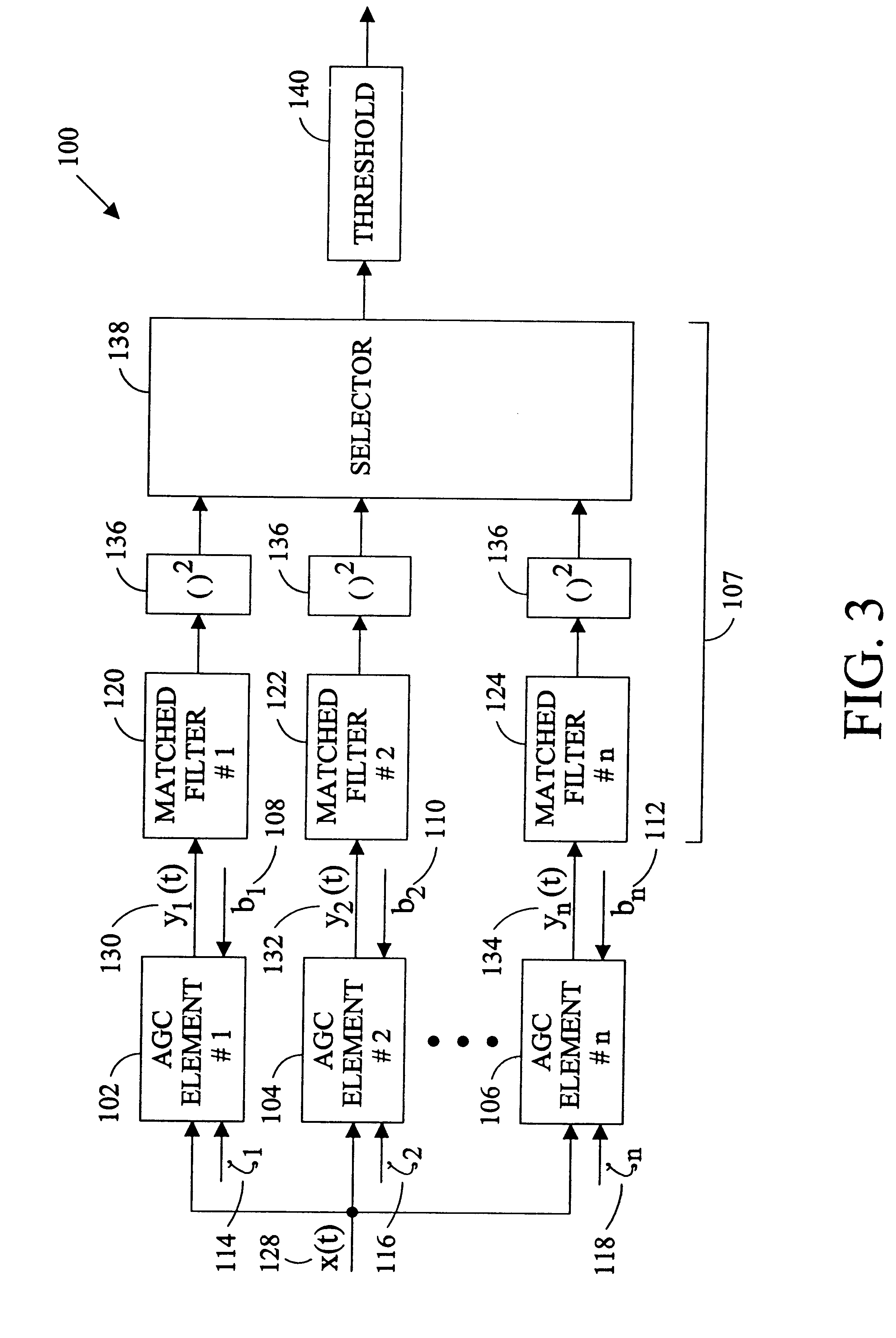
"The present invention provides an automatic gain control system for a digital radio that selects the output with the highest signal to noise ratio. The system includes multiple automatic gain control elements and a discriminator to select the output with the greatest signal to noise ratio. The system also includes a memory to store an integrator value used in earlier processing of the input signal. Each automatic gain control element has a different threshold value or bias, resulting in different effective dynamic ranges and signal distortion times. The output of each element is filtered by a matched filter to suppress all constituents of the signal except the reference signal. The system allows for rapid settling of one of the automatic gain control elements without high loop gain that causes signal distortion."

Problems solved by technology

However, a high loop gain distorts the signal leading to a loss of signal to noise ratio for the detector.
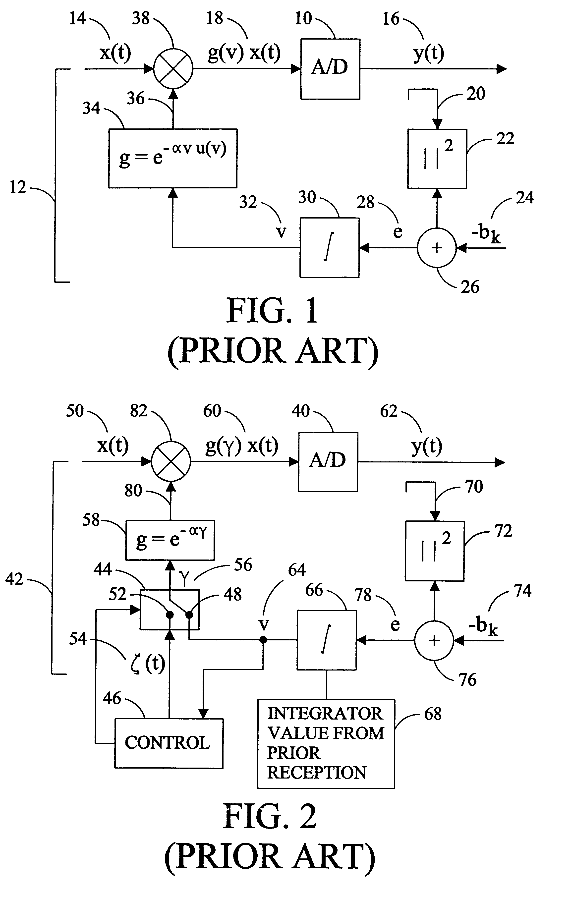
Obtaining the rapid settling time required by an IEEE 802.11a LAN with an acceptable signal distortion has not proven to be feasible with the classic AGC loop illustrated in FIG.
While the improved AGC provides better transient response, neither the classic AGC nor the improved AGC loop provides the rapid settling required to settle the AGC within the duration of the initial symbols of the preamble of the OFDM signal of the IEEE 802.11a LAN with an acceptable level of signal distortion.

Method used


Image

  • Rapid settling automatic gain control with minimal signal distortion
  • Rapid settling automatic gain control with minimal signal distortion
  • Rapid settling automatic gain control with minimal signal distortion

Examples


Embodiment Construction

The analog radio frequency (R / F) signal received at the antenna of a digital radio receiver is converted to the digital signal in which the message is encoded by a detector. The signal conversion is performed by an analog-to-digital (A / D) convertor of the detector. An A / D converter 10 and an associated automatic gain control loop (AGC) 12 (indicated by a bracket) of a digital radio detector is illustrated in FIG. 1. The A / D convertor 10 converts an analog R / F signal (x(t)) 14 received from an antenna and R / F amplifier (not illustrated) into a digital signal (y(t)) 16. In a detector, an output level detector (not illustrated) senses whether the signal to noise ratio of the digital signal has reached a predetermined threshold value. The automatic gain control (AGC) loop 12 controls input to the A / D converter 18 to prevent overshooting or undershooting the converter as the power of the input R / F signal 14 fluctuates over the dynamic range of the system. In an IEEE 802.11a LAN the dynam...


PUM


Abstract

An apparatus and method of automatic gain control (AGC) useful for a detector of a digital radio providing rapid settling and minimal distortion is described. The automatic gain control includes a plurality of modular AGC elements each having a unique bias. The AGC elements may also be switched from an open loop operating mode with a unique initial gain voltage to a closed loop operating mode. A matched filter is applied to the output of each of the AGC elements to filter out all but the signal constituents that match the reference symbol. The output of the matched filters having the greatest signal to noise ratio is the selected as the detector output. The output with the greatest signal to noise ratio corresponds to the output of the AGC element that has settled with the least distortion.

Description

BACKGROUND OF THE INVENTIONThe present invention relates to an automatic gain control apparatus and method and, more particularly, to a rapid settling automatic gain control that produces minimal signal distortion useful for a detector of a digital radio receiver.The detector of a digital radio receiver converts the analog radio frequency (R / F) signal received at the antenna to the digital signal in which the message is encoded. Conversion of the signal from analog to digital format is performed by an analog-to-digital (A / D) converter in the detector. While the amplitude of the received R / F signal can vary substantially, the amplitude variation of the signal at the input to the A / D converter must be narrowly controlled because the data detection circuitry requires a relatively constant amplitude input to avoid clipping and loss of data. The input to the A / D convertor is controlled by an automatic gain control (AGC) loop.The Institute of Electrical and Electronic Engineers (IEEE), DR...

Claims


Application Information

Patent Timeline
Patent Type & Authority Patents(United States)
IPC IPC(8): H03G3/30
CPCH03G3/3036
Inventor KOWALSKI, JOHN M.
Owner SHARP LAB OF AMERICA INC
Learn More