
Power amplifier sharing in a wireless communication system with amplifier pre-distortion

Inactive Publication Date: 2005-02-22
ALCATEL-LUCENT USA INC +1
View PDF7 Cites 106 Cited by
  • Summary
  • Abstract
  • Description
  • Claims
  • Application Information

AI Technical Summary

Benefits of technology

The present invention solves the above problems by forming the composite signals in the digital domain, i.e. using digital circuitry, so that digital pre-distortion can be used to pre-distort the composite signals to compensate for amplifier non-linearity. Although the prior art has been wedded to the idea of forming the composite signals in the analog domain so as to avoid having to phase and gain match the radios to produce acceptable antenna isolation tolerances, as mentioned above. Applicants have realized that in a system where amplifiers are shared the advantages of digital pre-distortion can outweigh those difficulties. Digitally pre-distorting signals that are amplified in shared amplifiers compensates for the non-linearity of the amplifiers without the expense, inefficiencies, and increased possibility of circuit failure of an analog feed-forward loop. Illustratively, the applicants propose that the radios can be designed to reduce the difficulties of phase and gain matching. For example, the radios can share the same clock and / or the radios can be implemented on the same circuit board.

Problems solved by technology

However, the fact that it must be implemented using analog circuitry leads to several problems.
One problem is that this circuitry is expensive.
Another problem is that it produces inefficiencies due to the current loses that result from the signal passing through the delay line and the coupler of the feed-forward loop.
A third problem is that analog circuitry is more prone to fail than digital circuitry.

Method used


Image

  • Power amplifier sharing in a wireless communication system with amplifier pre-distortion
  • Power amplifier sharing in a wireless communication system with amplifier pre-distortion
  • Power amplifier sharing in a wireless communication system with amplifier pre-distortion

Examples


Embodiment Construction

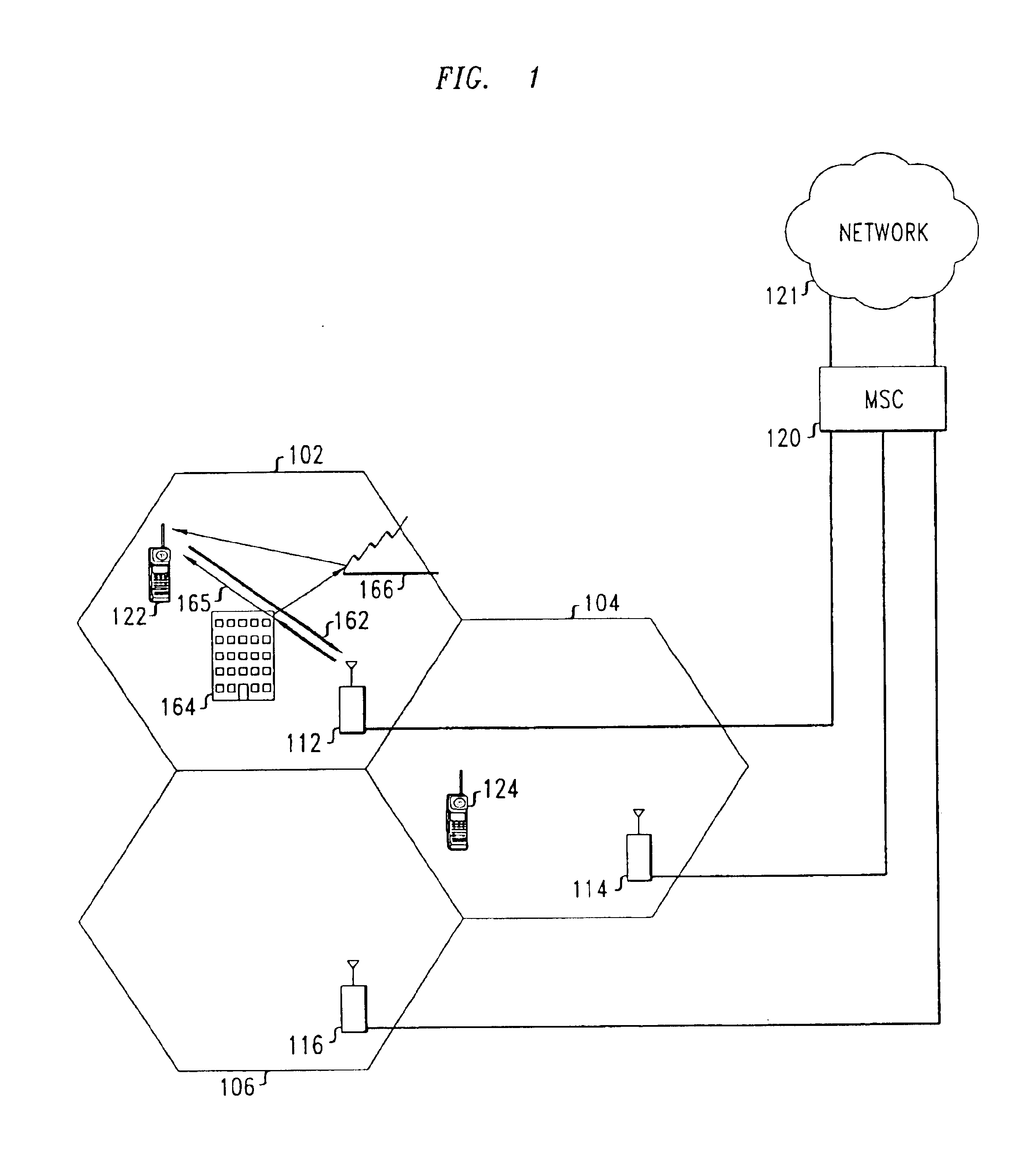
In conventional wireless communication system 100, shown in FIG. 1, a geographic area is divided into a plurality cells 102, 104, and 106. Each cell 102, 104, and 106 contains at least one base station 112, 114, and 116, respectively. Each base station 112, 114, and 116 includes equipment to communicate with mobile switching center (MSC) 120. MSC 120 is connected to local and / or long-distance transmission network 121, such as a public switched telephone network (PSTN). Each base station also includes equipment to communicate with mobile terminals, such as 122, 124. Each communication session with a particular mobile terminal is referred to as a “call.”

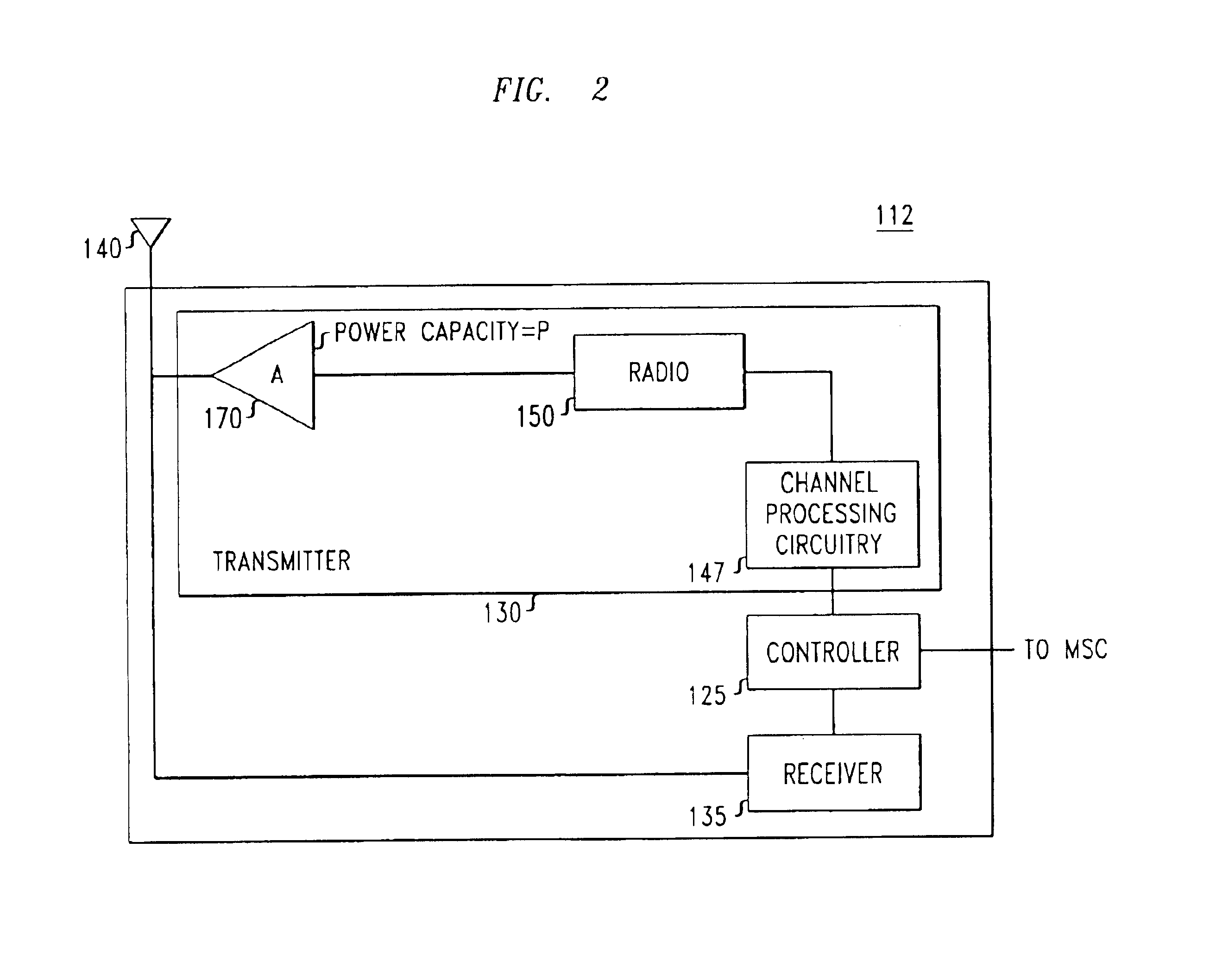
FIG. 2 shows base station 112 in more detail. Base station 112 includes controller 125 that is coupled to transmitter 130 and to receiver 135. Transmitter 130 and receiver 135 are coupled to antenna 140. Referring to FIGS. 1 and 2 the operation of base station 112 is now described. Digital signals are sent from MSC 120 to controller 12...


PUM


Abstract

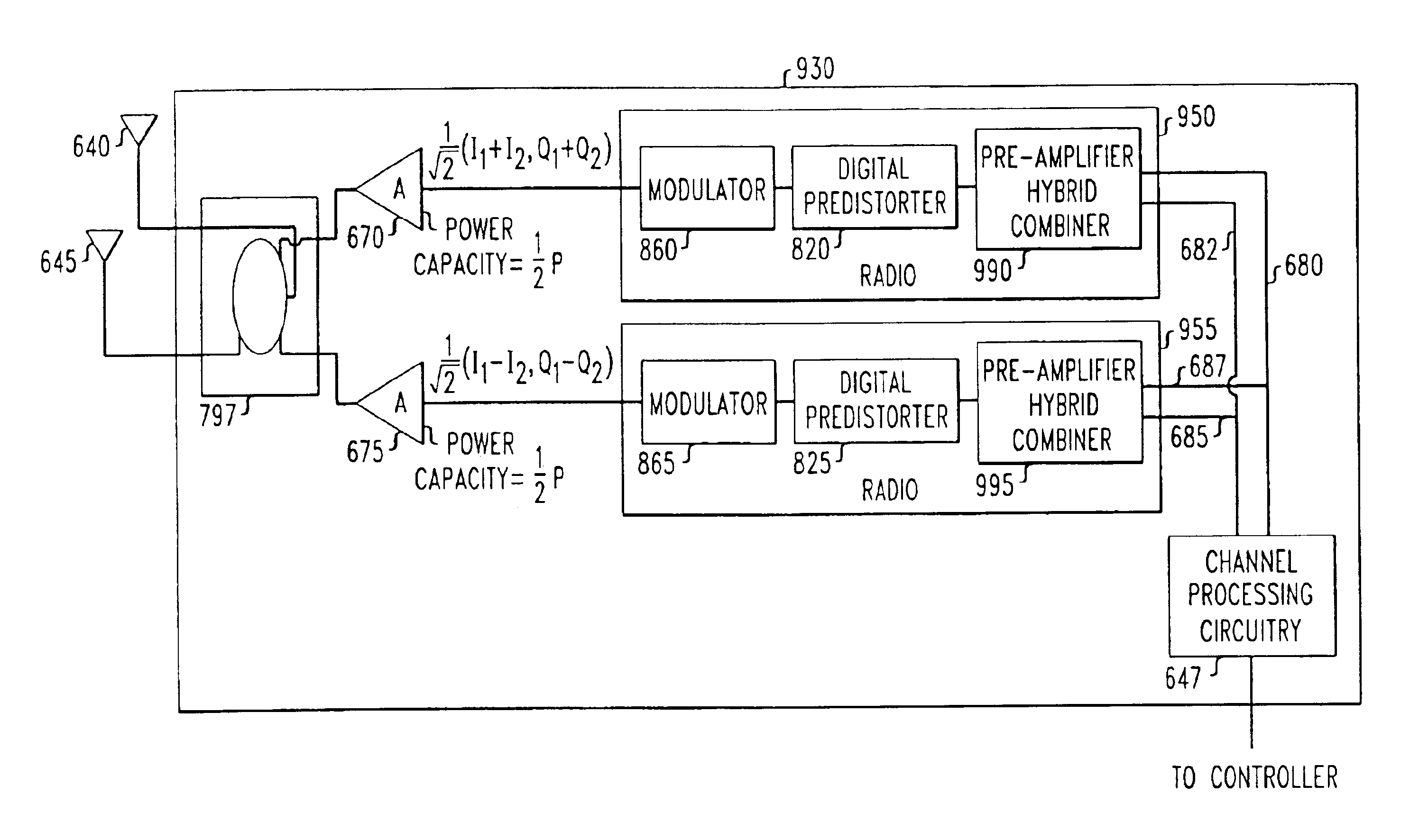
The technique of amplifier sharing is implemented in a system designed to accommodate transmit diversity. In one embodiment of the invention, the amplifiers are shared 1) to amplify a first and a second diversity-encoded signal, each of which represents the information a first signal that is to be transmitted using transmit diversity, and 2) to amplify a second signal to be transmitted without using transmit diversity. The first and second diversity-encoded signals are used to form a first and a second composite signal. Each composite signal is amplified in a different one of two power amplifiers. Each amplified composite signal is then used to form an amplified first diversity-encoded signal and an amplified second diversity-encoded signal. The first and second composite signals can also be formed using the second signal. Each composite signal is then amplified in a different one of the two power amplifiers and the two amplified composite signals are used to form an amplified second signal. In another embodiment of the invention, the first and second composite signals can be formed in the digital domain. Each composite signal is digitally pre-distorted and then modulated onto a transmission frequency signal, such as an RF signal. Each pre-distorted composite signal is then amplified in the respective amplifier.

Description

BACKGROUND OF THE INVENTION1. Field of the InventionThis invention relates to amplifier pre-distortion, and more particularly amplifier pre-distortion and efficient use of amplifier power capacity, for example, in a wireless communication system.2. Description of Related ArtAmplifier sharing is a useful technique in many signal-processing contexts. In a typical application of this technique, several original signals are used to form composite signals of equal power. Each of the composite signals is amplified in a respective amplifier. Thus, even if one of the original signals has a much larger power than the other original signals, because the composite signals have equal power, the amplifiers can have an equal power capacity, and that power capacity can be smaller than that of a single amplifier that had to amplify the original signal with the much larger power. This allows the amplifiers to be used more efficiently than would be the case if the respective amplifiers had amplified ...

Claims


Application Information

Patent Timeline
IPC IPC(8): H03F3/60H03F1/32H04B7/005H04B1/04
CPCH03F1/3241H04W52/42H04B1/0475H03F3/602
Inventor MA, ZHENGXIANGPOLAKOS, PAUL ANTHONY
Owner ALCATEL-LUCENT USA INC
Learn More