
Method for carrying out transactions and device for realizing the same

a technology of electronic payment and method, applied in the field of electronic payment system, can solve the problems of insufficient reliability of known tamper resistance technology to thwart such a risk, extreme instability, and disastrous effects on the entire system, and achieve the effect of effective and reliable payment mechanism

Inactive Publication Date:
View PDF138 Cites 15 Cited by
  • Summary
  • Abstract
  • Description
  • Claims
  • Application Information

AI Technical Summary

Benefits of technology

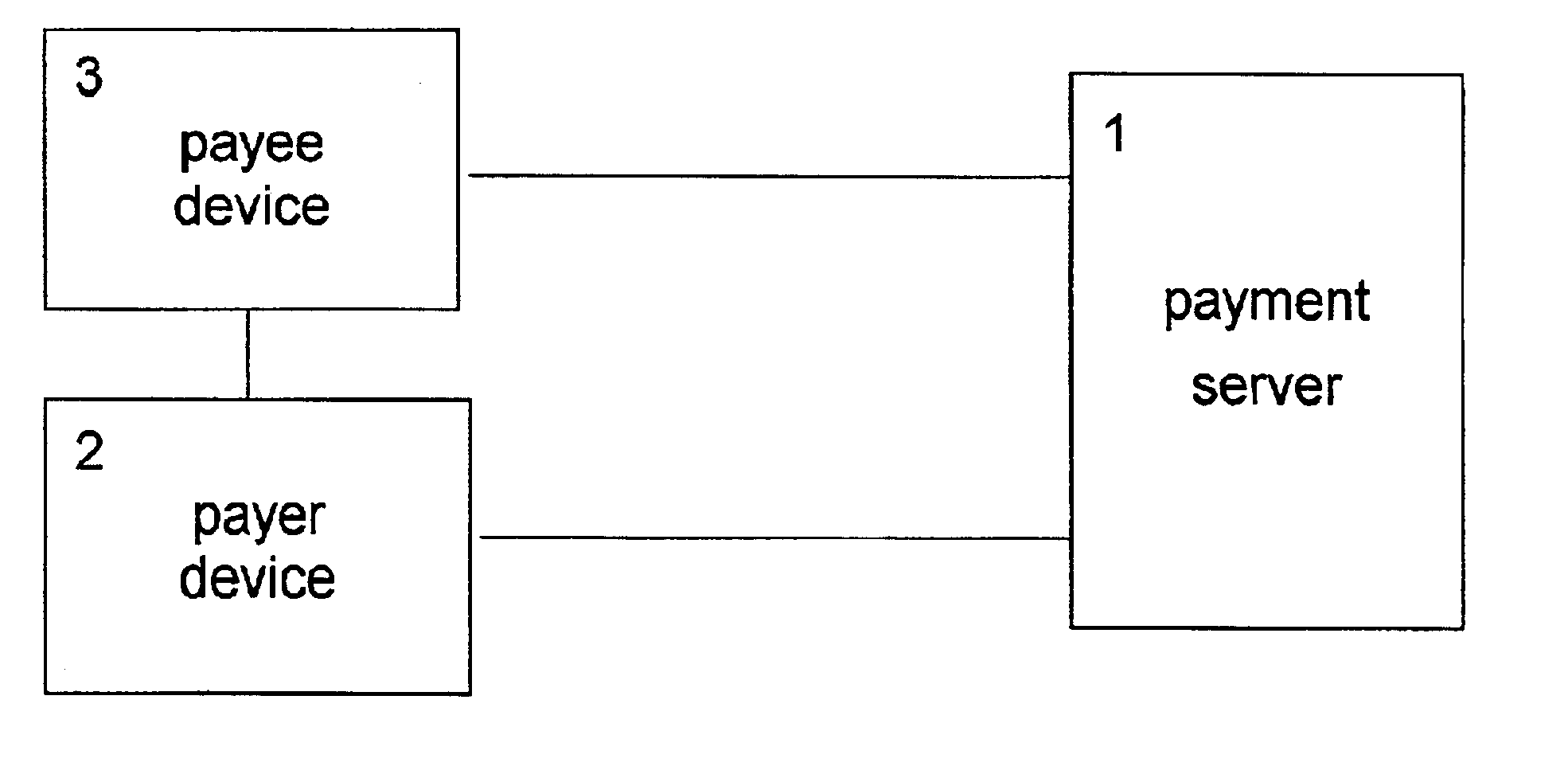
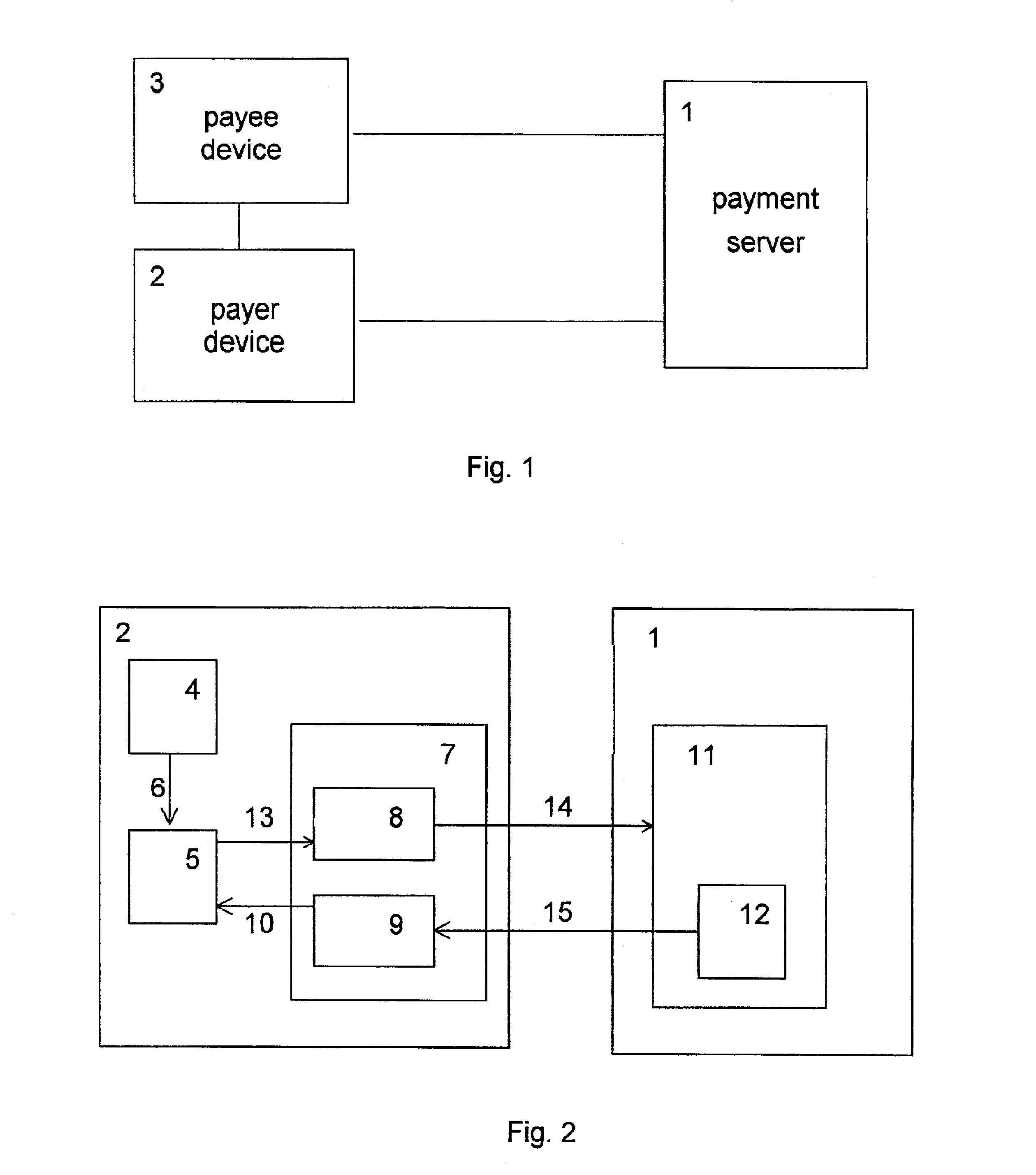
The main problem solved by the variants of the claimed invention is to create methods for effecting payments which would ensure an effective and reliable mechanism of paying via open communication nets, protection of each participant of the payment system from the other participants' cheating, privacy protection for ordinary participants of payments, and a wide range of payments.
Another advantage of performing the payment operation involving a payment certificate in comparison to the same payment operation with annulment of a payment certificate, in which one uses a collection of payment certificates, is that the time taken to effect a payment depends only on the speed of action of the net connections, and not on the payment amount, because the fixed size of payer orders makes it possible to indicate any practically possible amount of money as the payment amount.

Problems solved by technology

The deficiency of systems using this approach is that they are extremely unstable.
The matter is that penetration into one payer device can lead to disastrous effects for the entire system, because the data contained in the payer device allow one to spend arbitrary amounts of unpaid electronic cash.
Known tamper resistance technologies are not sufficiently dependable to thwart such a risk.
The deficiency of this method is that it does not prevent the multiple spending of payment certificates, and only allows one to detect such a spending and to make a certain payer responsible for it.
Thus, if the cheater is out of reach, then the payment system operator will incur losses.
In addition, an honest payer's reputation can suffer if a cheater has gained information on his payment certificates and used such a certificate.
Here, the bank does not know which one of the two modes is used by the payer, which fact promotes untraceability of payments.
However, the known method does not provide complete untraceability of a participant of the system if he is mostly a payer and not a payee, because the electronic coins given to such a participant and produced by the shop for exchange are evidence, generally speaking, that the participant made a payment to the shop.
The deficiencies of the known method are in that the bank's reputation is not defended against dishonest clients, and a client's money is not defended against a dishonest bank, because a dishonest client having received the bank's refusal to acknowledge an already used certificate for the second time can accuse the bank of cheating.
In turn, a dishonest bank having received a certificate for verification may claim that the certificate has already been used before.
In addition, the bank has to store information on each of the used certificates in databases with sufficiently fast access, which leads to a rapid growth of the bank's databases and to the necessity of employing expiration dates for certificates.
Furthermore, in the known method the payment amount is an integral combination of nominal values of coins, which fact either limits the range of payments, or leads to the growth of the number of the coins used in payments, which also leads to the growth of the bank's databases and slows down the payments.
The deficiency of the known apparatus for effecting payments is that it does not prevent the multiple spending of payment certificates, and only allows one to detect such a spending and to make a certain payer responsible for it.
Another deficiency of the known apparatus for effecting payments is that it works slowly, which is caused by the large size of the data transmitted via communication nets.

Method used


Image

  • Method for carrying out transactions and device for realizing the same
  • Method for carrying out transactions and device for realizing the same
  • Method for carrying out transactions and device for realizing the same

Examples


example 1

As the money signature system, one uses a system based on the digital RSA-signature (B. Schneier, Applied Cryptography: Protocols, Algorithms, and Source Code in C, John Wiley&Sons, New York, 2nd edition, 1996 and A. J. Menezes, P. C. Van Oorshot, S. A. Vanstone, Handbook of Applied Cryptography, CRC Press, 1997). In this system, a secret key is the pair (N, D), where D is a secret exponent and N is the modulus. Here, the corresponding public key is a pair (N, E), where E is a public exponent satisfying the condition XE·D=1 (mod N) for each integral number X coprime to N. The RSA system allows several methods of making a blind digital signature. For example, one of these methods is described in the patent: D. Chaum, Blind Signature Systems, U.S. Pat. No. 4,759,063, 19 Jul. 1988, and another one is described in the patent: D. Chaum, Blind Unanticipated Signature Systems, 15 U.S. Pat. No. 4,759,064, 19 Jul. 1988.

As an admissible level, one takes an arbitrary collection of nonnegative ...

example 2

The preparatory actions are performed as in Example 1 described above.

The payee, who is a seller in the present example, opens an account with public key ES in the bank as described above. Further, in the storage device of the seller's “Electronic wallet” one creates a record with information about the opened account, which information contains the secret key DS corresponding to the public key ES, the number AccountId of the opened account, and other attributes of the account.

In this example, the replenishment source of the payer1s “Electronic wallet” is the payer's account, which he opens in exactly the same way as the payee. The payer delivers a certain amount of money to the account opened by him by a postal money order; for the sake of definiteness, let it be 200 dollars.

Using the opened account as the replenishment source, the payer replenishes his “Electronic wallet” with the help of the operation of primarily filling a payment certificate.

During the operation of primarily fil...

example

In this example, we use agreements and notation adopted in Example 1 described above.

The operation of replenishing the payment certificate, i.e., the operation of obtaining a payment certificate signature whose level exceeds the level of the payment certificate signature contained in the payer device at the beginning of the replenishment operation, is performed by obtaining the blind money signature of the operator. Here, as the initial data one takes the payment certificate signature contained in the payer device. Suppose that the payer's “Electronic wallet” contains a payment certificate with signature S1 of level (0, 2, 30). Suppose that the value of this payment certificate, which is equal to 2 dollars and 30 cents in the present case, is not sufficient for the payer to make a certain purchase. In order to make this purchase anyway, the payer replenishes his “Electronic wallet” by replenishing the payment certificate.

For this purpose, one delivers the blinded signature S1 of the...


PUM


Abstract

A method for effecting payments is suggested which allows protecting the financial interests of each participant of a payment during payments via open telecommunication nets from other participants' cheating, provides protection of the payers' and payees' privacy, admits payments ranging from micro-payments to business-to-business payments, ensures that the time taken to effecting a payment depends only on the speed of action of the net connections and not on the payment amount, makes it possible to serve of serving a number of clients which grows proportionally to the payment system operators resources, is easy to build into an arbitrary trade system, enables each client both to pay and to receive payments, and makes possible payments between clients of different banks. The method of effecting payments is realized with the help of programming means.

Description

BACKGROUND OF THE INVENTION1. Field of the InventionThe invention relates to electronic payment systems.2. Description of the Related ArtElectronic payment systems are intended to provide an adequate payment means for effecting transactions via open communication nets. Besides the degree of security and reliability, the cost of servicing, the rapidity of performing main operations, etc., an important characteristic of a payment system is the protection of user's privacy. A user's privacy implies that nobody, not even the payment system operator, can control the user's purchases. One of the ways of protecting privacy in electronic payment systems consists in that purchases are made with the help of digital data, which confirm the solvency, but do not lead to the identification of the payer. Such data are sometimes called electronic cash. However, electronic cash, as well as any digital data, can easily be copied, so that one must take care to prevent multiple spending of electronic c...

Claims


Application Information

Patent Timeline
Patent Type & Authority Patents(United States)
IPC IPC(8): G06Q20/00G07F7/10G06Q30/06G06Q20/16G09C1/00H04L9/00H04W12/00
CPCG06Q20/02G06Q20/04G06Q20/085G06Q20/3674G07F7/1016G06Q20/3821G06Q20/3825G06Q20/3829G06Q20/382
Inventor ZOLOTOREV, OLEG ANATOLIVICHKUZNETSOV, IVAN VLADIMIROVICHMOSHOKIN, ANDREY GENNADIEVICHSMIRNOV, ALEXANDR LEONIDOVICHKHAMITOV, ILDAR MAGAFUROVICH
Learn More