
Hybrid flying wing

a hybrid flying and wing technology, applied in the field of aircraft, can solve the problems of high stress on the wing structure, no existing aircraft can cost-effectively deliver substantial payloads up to hundreds or even thousands of tons over a long distance, and achieve the effects of low pressure intensity, high structural efficiency and low cos

Inactive Publication Date: 2005-03-01
CHEN ZHUO
View PDF53 Cites 82 Cited by
  • Summary
  • Abstract
  • Description
  • Claims
  • Application Information

AI Technical Summary

Benefits of technology

The fundamental object and advantage of my invention is to build an aircraft that is highly flexible and cost-effective in transporting payload. Specifically, the objects and advantages of an aircraft based on my invention are:1. Can cost-effectively fly over long distances;2. Can cost-effectively achieve V / STOL;3. Can transport substantial payload of large dimensions;4. Can taxi and move around on unprepared, unpaved grounds;5. Can achieve high structural efficiency with low-cost, conventional structures made of lowcost, conventional materials;6. Can achieve effective flight control with systems that are easy to develop and operate.
The control during V / STOL is also easy to achieve because the large wing area makes it possible to house one or more lift-fan propulsion systems. By adjusting the thrust of different lift-fan propulsion systems, the aircraft can achieve balance during hovering and flying at very low speed. If only one lift-fan propulsion system is installed, the wingtip hulls can balance the aircraft by adjusting their forward and after ballonet systems. By adjusting the angle of the moveable louvers of the louver-covers of the lift-fan propulsion systems, the aircraft can achieve the transition between hovering and horizontal flight.

Problems solved by technology

Yet, no existing aircraft can cost-effectively deliver substantial payload up to hundreds or even thousands tons of payload over a long distance to a place that only has a short, rough, and dirt runway or does not have a runway at all.
However, a major shortcoming of the tube-and-wing design makes it technically difficult to build even bigger aircraft.
This causes high level of stress over the wing structure.
The stress becomes even greater for aircraft with heavy payload and makes the tube-and-wing design structurally inefficient for aircraft with substantial payload.
In addition, transportation aircraft of tube-and-wing design are very difficult to realize vertical and / or short take-off and landing (V / STOL), especially for aircraft of heavy payload.
Although Boeing C-17 can take off from a 2,315 meters (7,600 feet) long rough, dirt runway, it can only carry 72.6 tons (160,000 pounds) of payload to achieve this take-off distance and is very expensive at an average unit price of $198 million (1999 dollars).
The large wingspan makes a large BWB aircraft difficult to move around in small or crowded airports.
This weight makes a big BWB aircraft of substantial payload either has to carry large and heavy landing gears to move on unprepared runways or be restricted to take-off and land in a limited number of big airports.
Thirdly, BWB aircraft with heavy payload are difficult to achieve V / STOL.
In addition, the huge size and buoyant nature of lighter-than-air aircraft make it difficult to control under windy weather conditions.
These devices do not generate aerodynamic lift.
In addition, they are difficult to control under windy weather conditions.
However, existing inventions cannot utilize static and aerodynamic lift to a degree that the means for generating both kinds of lift can effectively and efficiently benefit from each other and the aircraft can be easy to control, cost-effective to operate, and easy to develop and build.
This design is not efficient in horizontal flight because its lifting body makes high induced-drag while generating aerodynamic lift.
In addition, an aircraft of this invention is very difficult to control.
There are simply too many functions for the tilt prop-rotors to perform in every portion of flight and such a propulsion system must be complex, costly to develop, and difficult to operate and maintain.
Finally, both the two kinds of propulsion systems of this invention make an aircraft of this design structurally inefficient.
The large number of lift fans not only add a significant amount of weight to the aircraft but also increase the complexity of both the propulsion and flight control systems.
Such a big number of lift funs and the complexity of the propulsion and control systems make the aircraft structurally heavy, costly to build, and difficult to maintain.
Such a concentration of load makes the four tilt-able outriggers structurally heavy.
Such a structure arrangement also adds weight to the aircraft structure.
For the same reasons mentioned above about the tile-able prop-rotors of U.S. Pat. No. 5,823,468, the four tilt-able propulsion units of invention U.S. Pat. No. 6,286,783 B1 make the aircraft difficult to control and structurally inefficient.
This design still has high induced-drag during horizontal flying because its semi-rigid lifting body has low aspect-ratio.
The design is structurally inefficient similar to a tube-and-wing aircraft because a big portion of load of the fuselage should be transferred to the middle portion of the wing and the wing structure should transfer the wing lift to the middle wing as well.
The design also does not have VTOL capability.
This design is structurally heavy and difficult to control because first, the large number of rotors need complicated power transmission and control systems; second, installing rotors on the trailing edge, the thinnest and slenderest portion of the wings, makes the wing structurally heavy.
Although this design makes a tube-and-wing aircraft have a smaller wing than conventional tube-and-wing aircraft, the structural disadvantages of tube-and-wing design remain.
In addition, the design does not have VTOL capability.
This design has high drag during flying because its non-lift-generating freight compartment has a flat and long shape, which has big wetted area for generating drag.
The design also does not have VTOL capability.
However, the concentration of load onto a few number of rotor hubs makes helicopters structurally inefficient when carrying substantial payload.
In addition, the fact that a significant portion of engine power is consumed to generate vertical lift during horizontal flight makes helicopters economically inefficient when flying over a long distance.
However, these attempts cannot resolve the above-mentioned structural disadvantage of load concentration because the rotors still generate all the lift during VTOL.
Tilt rotor aircraft like V-22 has the same structural disadvantage as helicopters, which is a significant shortcoming when carrying substantial payload.
In addition, a complex control system is required to balance the aircraft while tilting and controlling the rotors.
Such a control system is costly to develop.
This mechanical system is heavy and increases the cost and maintain burden of the aircraft.

Method used


Image

  • Hybrid flying wing
  • Hybrid flying wing
  • Hybrid flying wing

Examples


Embodiment Construction

—PREFERRED EMBODIMENT

General Description

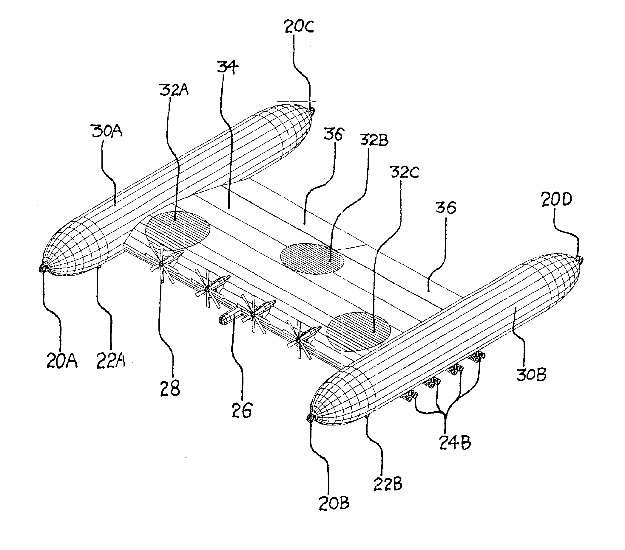
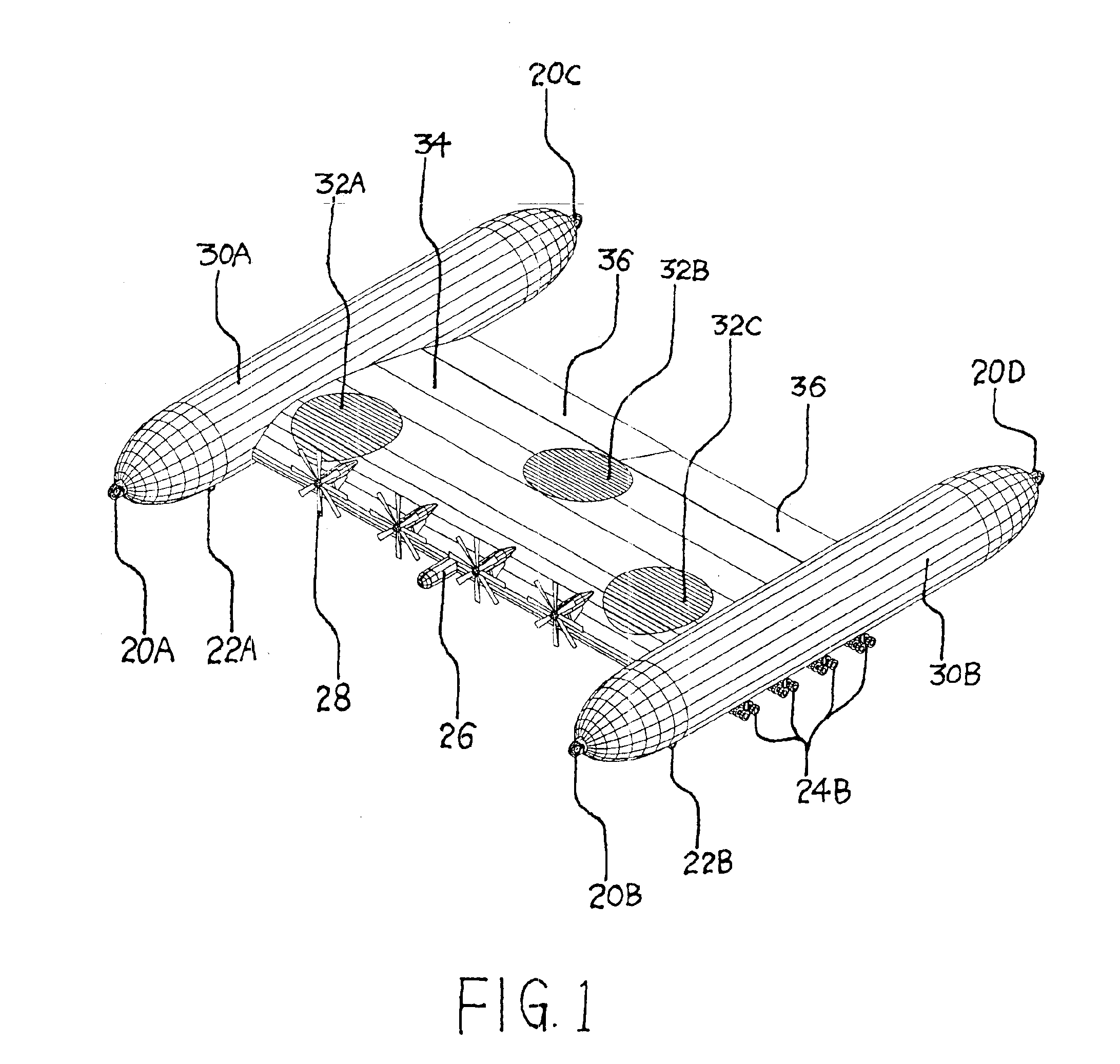
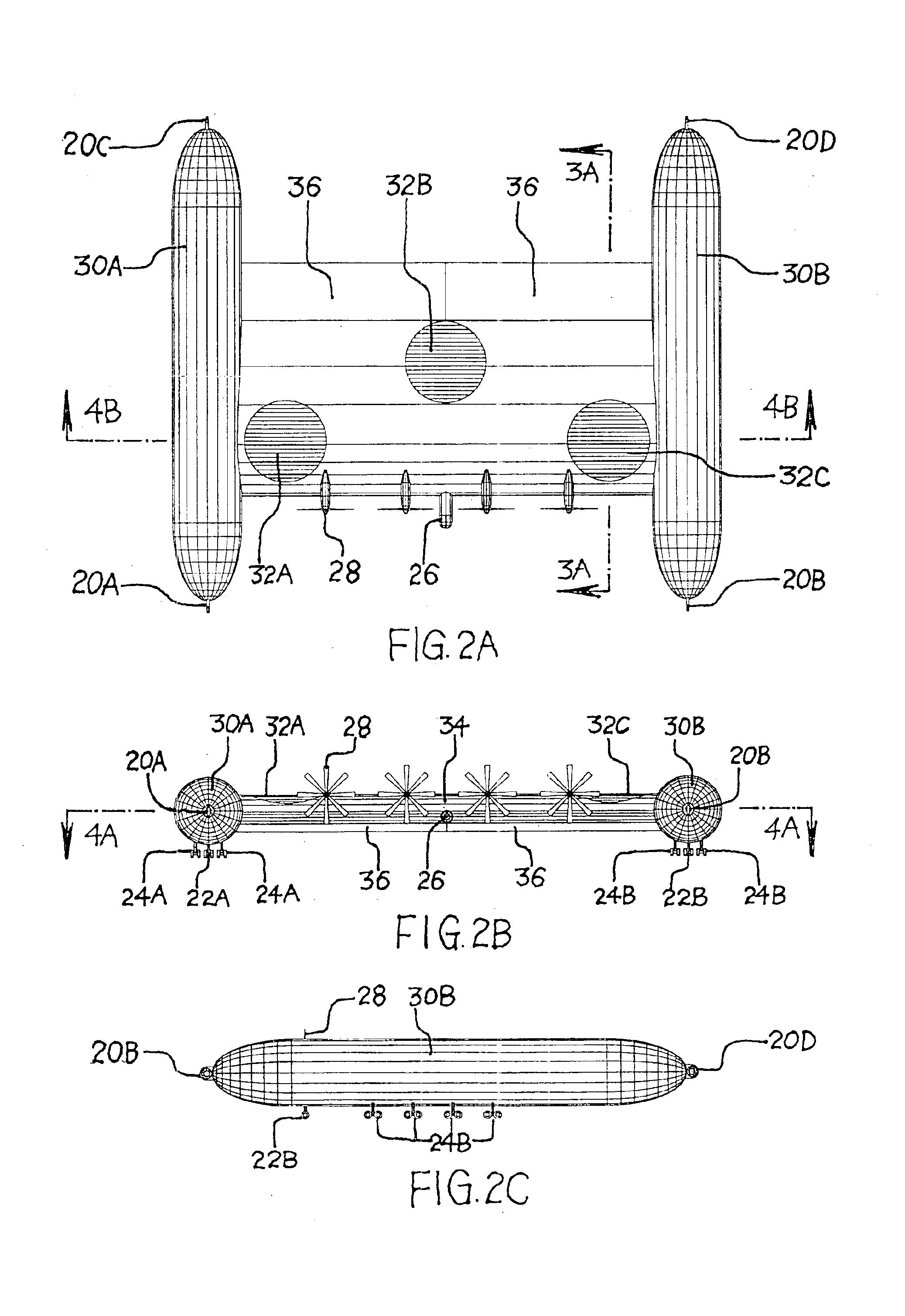
FIGS. 1, 2A, 2B, and 2C show the configuration of the preferred embodiment of the Hybrid Flying Wing aircraft, also called the “aircraft”, according to the invention. The aircraft is composed of a wing 34 and two wingtip hulls 30A and 30B installed on both wingtips of the wing. Wing 34 carries payload, fuel, and major systems. Forward propulsion systems 28 are installed in the upper-front of wing 34. Three lift-fan propulsion systems are installed on wing 34. The upper louver-covers 32A, 32B, and 32C for these three lift-fan propulsion systems are indicated in the figs. Right lift-fan propulsion system with its upper louver-cover 34A is positioned in the right-front side of wing 34; left lift-fan propulsion system with its upper louver-cover 34C is located in the left-front side of wing 34; center lift-fan propulsion system with its upper louver-cover 32B is positioned in the middle-rear side of wing 34. All the three lift-fan propulsion syste...


PUM


Abstract

An aircraft has a flying wing and two wingtip hulls installed on the wingtips of the flying wing. Both of the wingtip hulls contain lighter-than-air gas to generate static lift. These wingtip hulls not only contribute to lift-generating but also help the aircraft achieve roll stability and control. Forward propulsion systems are installed at the upper-front positions of the flying wing. When vertical and / or short take-off and landing (V / STOL) capability is required, one or more lift-fan propulsion systems can be installed on the flying wing. The lift-fan propulsion systems can either be driven by their own engines or by the power transmitted from the forward propulsion systems. Payload can be carried inside the flying wing or be hung under or held above the flying wing.

Description

CROSS-REFERENCE TO RELATED APPLICATIONSNot ApplicableFEDERALLY SPONSORED RESEARCHNot ApplicableREFERENCE TO SEQUENCE LISTING, A TABLE, OR A COMPUTER PROGRAM LISTING COMPACT DISK APPENDIXNot ApplicableBACKGROUND OF THE INVENTION—FIELD OF INVENTIONThe invention relates to the field of aircraft and, in particular, to aircraft incorporating both aerodynanic and static lift.BACKGROUND OF THE INVENTION—DESCRIPTION OF PRIOR ARTAircraft has been serving the world for about 100 years and proven useful in many applications. Yet, no existing aircraft can cost-effectively deliver substantial payload up to hundreds or even thousands tons of payload over a long distance to a place that only has a short, rough, and dirt runway or does not have a runway at all. The following paragraphs explain why prior art cannot fulfill this need.Tube-And-Wing AircraftModern transport aircraft are of tube-and-wing design. Antonov AN-225, the biggest modem transport aircraft, can carry 250 tons (550,782 pounds) of...

Claims


Application Information

Patent Timeline
IPC IPC(8): B64B1/00B64B1/06B64B1/32B64B1/34B64C29/00
CPCB64B1/06B64B1/32B64B1/34B64C29/0025B64B2201/00B64D2211/00Y02T50/69Y02T50/50B64D27/353
Inventor CHEN, ZHUO
Owner CHEN ZHUO
Learn More