Method for manufacturing a workpiece using a magnetron sputter source

a technology of magnetron sputter and workpiece, which is applied in the direction of electrolysis components, vacuum evaporation coatings, coatings, etc., can solve the problems of reduced utilization of target materials, special problems, and uneven thickness distribution of substrate layers, and achieve high sputter rates and good achievable distribution values. , the effect of high sputter ra

Inactive Publication Date: 2005-03-01
OERLIKON ADVANCED TECH +1
View PDF5 Cites 11 Cited by
  • Summary
  • Abstract
  • Description
  • Claims
  • Application Information

AI Technical Summary

Benefits of technology

The present invention therefore has as its object to eliminate the disadvantages of prior art. In particular, the present invention has as its object to realize a magnetron sputter source with elevated outer pole magnet configuration, which combines the advantages of high sputter rates at high degrees of material utilization with very good achievable distribution values on the substrate during the entire target service life, at stable and reproducible conditions. In addition, the magnetron sputter source has high overall economy.

Problems solved by technology

In such a magnetron discharge typically an annular erosion trench is generated during operation whereby also problems in the layer thickness distribution on the substrate result and have to be solved.
A further disadvantage is that through the developing trench-form erosion pattern of the target the utilization of the target material becomes reduced.
In configurations in which the substrates are disposed stationarily opposite the magnetron target or rotate about their internal axes in a plane in front of the target, or in which already in the substrate plane over a maximally large area high homogeneity requirements of the coating must be met, special problems are encountered since the distribution and the material utilization problematic must primarily be solved already at the source side and cannot be solved by moving the substrate past such source.
As stated, through the annular plasma loop a pronounced annular erosion trench is developed in the target, which leads to problems with the layer distribution on the substrate at high precision requirements.
The relatively large target substrate distance as well as also the relatively large oversizing of the target diameter practically led to the fact that the utilization of the material sputtered off was overall poor.
In a stationary coating configuration of substrate s this source formation has the disadvantage that, on the one hand, relatively large target to substrate distances are necessary, the utilization of the sputtered material which arrives on the substrate s is relatively low, since the zones in the outer region, which cannot be utilized, are proportionally large and the target utilization is lower than in rotating systems.
This results in the sputtered material being transferred to a very large extent onto the substrate and the margin losses being low.
Certain restrictions however occur thereby that the control of the erosion profile and of the distribution and the attainment of reproducible conditions, in particular over the target service life, is difficult in this respect.
At very high required distribution requirements and material utilization degrees this method has, however, certain restrictions.

Method used


Image

  • Method for manufacturing a workpiece using a magnetron sputter source
  • Method for manufacturing a workpiece using a magnetron sputter source
  • Method for manufacturing a workpiece using a magnetron sputter source

Examples


Embodiment Construction

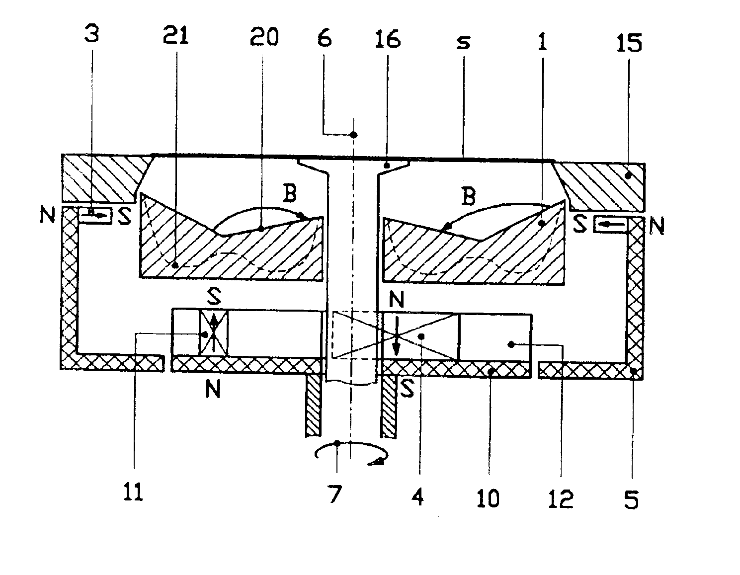
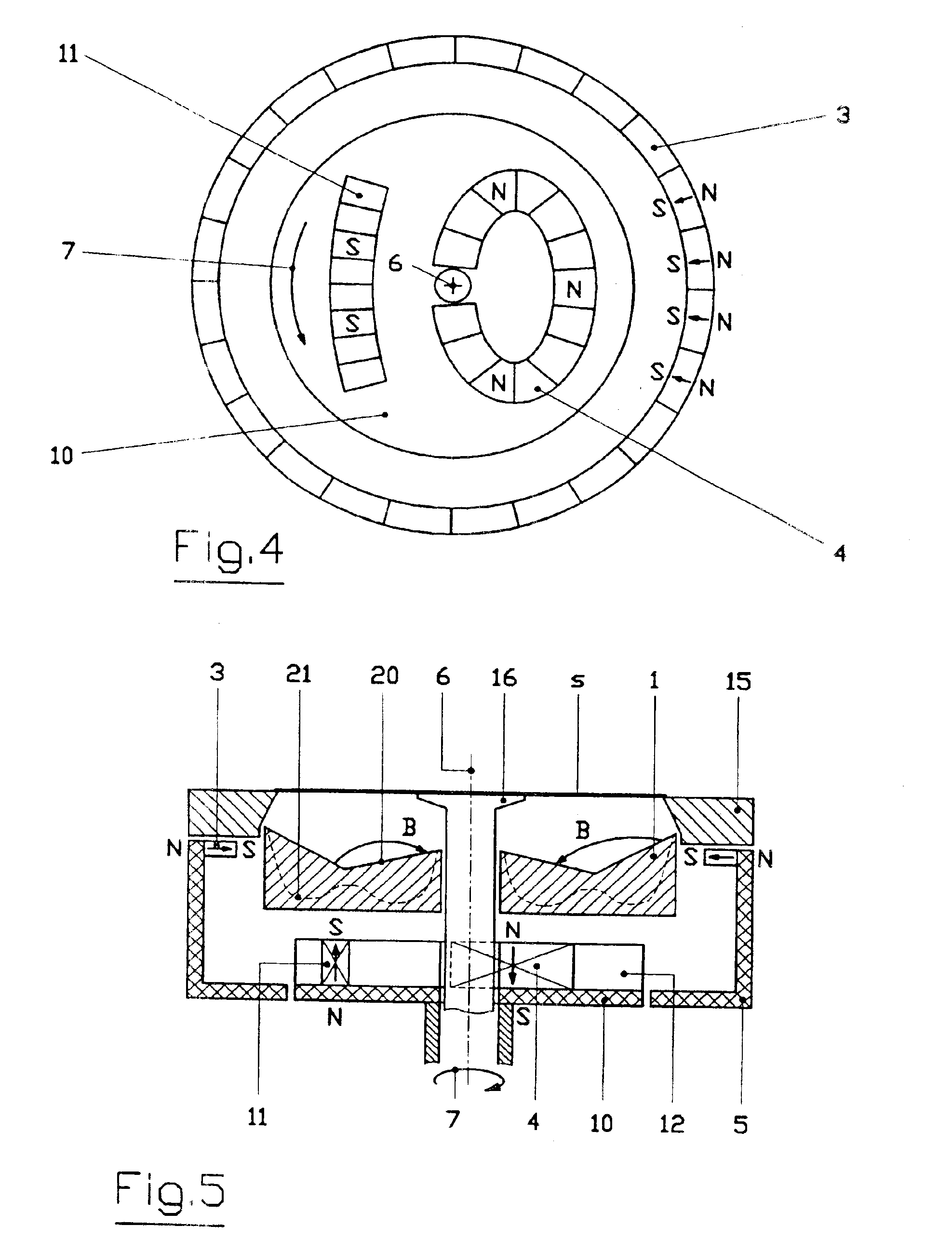
FIG. 5 depicts a magnetron sputter source in cross section and schematically. The sputter target 1 is developed as an annular target body, which has substantially a concavely developed sputter face 20. The sputter face 20 can per se also be developed such that it is planar, but the concave development is significantly more advantageous since with small substrate distance d the discharge volume comprises essentially the sputter face 20 and the substrate face s and thus the loss zone in the margin region is minimal. The round target 1 for coating storage plates s is advantageously developed such that it is annular which permits guiding an electrode 16 through in the center along the source center axis, which serves simultaneously as center mask for the disk-form substrate s. The substrate s is disposed at a small distance d from target 1 and the diameter of target 1 is only slightly greater than the diameter of substrate s. The discharge volume formed thereby is delimited by an electr...


PUM

PropertyMeasurementUnit
distanceaaaaaaaaaa
diameteraaaaaaaaaa
distanceaaaaaaaaaa

Abstract

A workpiece is manufactured using a magnetron source that has an optimized yield of sputtered-off material as well as service life of the target. Good distribution values of the layer on the workpiece are obtained that are stable over the entire target service life, and a concave sputter face in a configuration with small target-to-workpiece distance is combined with a magnet system to form the magnetron electron trap in which the outer pole of the magnetron electron trap is stationary and an eccentrically disposed inner pole with a second outer pole part is rotatable about the central source axis.

Description

FIELD AND BACKGROUND OF THE INVENTIONThe invention relates to a method for manufacturing a workpiece using magnetron sputter source.Magnetron sputter sources of this type have been known for many years and serve for coating substrates in a vacuum. Such magnetron sputter sources are distinguished in that with the aid of a magnetic field a dense plasma is generated in front of the target surface to be sputtered, which permits sputtering the target through ion bombardment at high rates and attaining a layer on the substrate with high growth rate. In such magnetron sputter sources the magnetic field serves as an electron trap which determines significantly the discharge conditions of the gas discharge and plasma confinement. The magnetic field of such a magnetron electron trap is developed such that in the region of the back side of a target to be sputtered closed magnetic pole loops are disposed which do not intersect and, in special cases, form an annular configuration and can also be...

Claims


Application Information

Patent Timeline
Patent Type & Authority Patents(United States)
IPC IPC(8): H01J37/32H01J37/34C23C14/35G11B7/26
CPCH01J37/3408
Inventor HEINZ, BERNDDUBS, MARTINEISENHAMMER, THOMASGRUNENFELDER, PIUSHAAG, WALTERKADLEC, STANISLAVKRASSNITZER, SIEGFRIED
Owner OERLIKON ADVANCED TECH
Why Eureka
Try Eureka