Funnel for cathode ray tube

a tunnel and cathode ray tube technology, applied in the field of tunnels, can solve the problems of increasing reducing the temperature of the glass filled in the open end portion in the vicinity of the diagonal axes, and reducing the time required for filling, so as to reduce the time required, increase the press pressure, and reduce the effect of cracks

Inactive Publication Date: 2005-03-01
NIPPON ELECTRIC GLASS CO LTD
View PDF5 Cites 1 Cited by
  • Summary
  • Abstract
  • Description
  • Claims
  • Application Information

AI Technical Summary

Benefits of technology

Because the body portion of the funnel for a cathode ray tube of the present invention has a shape proper for press molding, the pressing and extending of the glass becomes smooth during the press molding. As a result, small cracks due to the delay of the pressing and extending of the glass are restrained from generating on the open end portion in the vicinity of the diagonal axes. Also the problems such as the increase of the time required for fill-up, and the increase of the press pressure are solved.
The scratches generated on the outer surface at the diagonal axes of the body portion by handling the funnel are restrained. The vacuum stress generated in the stage of forming the cathode ray tube is distributed. As a result, an excellent effect of restraining the possibility of a breakage of the funnel or the cathode ray tube is obtained.

Problems solved by technology

However, since a resistance against the pressing and extending increases at the ridge-like corner shapes, the fill-up of the glass up to the open end portion is delayed at the corner shapes in comparison with the rest portions.
Since the fill-up is delayed on the diagonal axes in this way, the temperature of the glass filled in the open end portion in the vicinity of the diagonal axes decreases, so that the problems such as generation of small cracks in the glass, increase of time required for the fill-up, or increase of pressing pressure occur.
The ridge-like corner shapes are also disadvantageous in terms of strength.
Namely, scratches generated as a result of handling the funnel tend to concentrate at the ridge-like corner shapes.
It is undeniable that the cathode ray tube may break depending on degree of the scratches and the vacuum stress.

Method used


Image

  • Funnel for cathode ray tube
  • Funnel for cathode ray tube
  • Funnel for cathode ray tube

Examples


Embodiment Construction

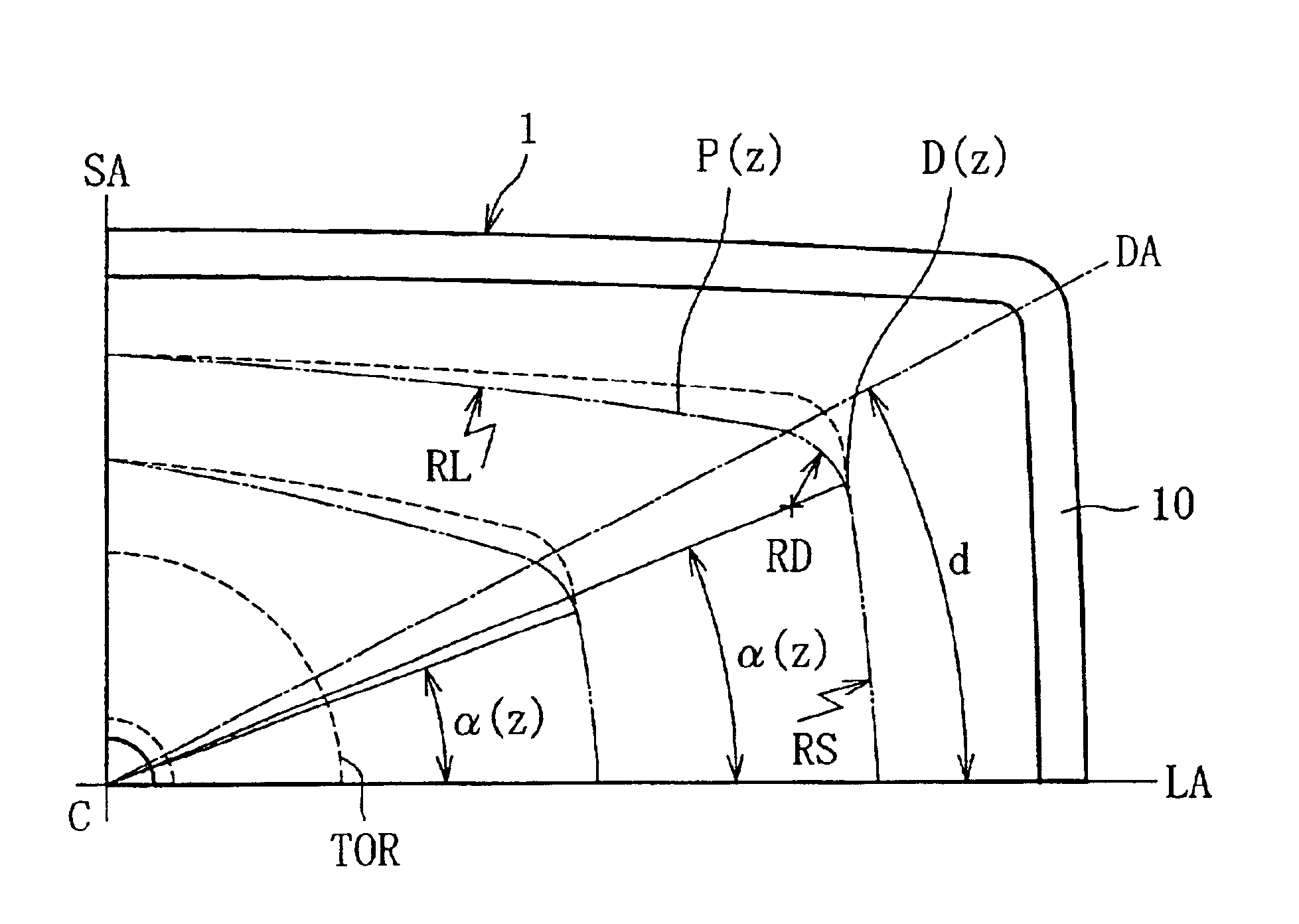
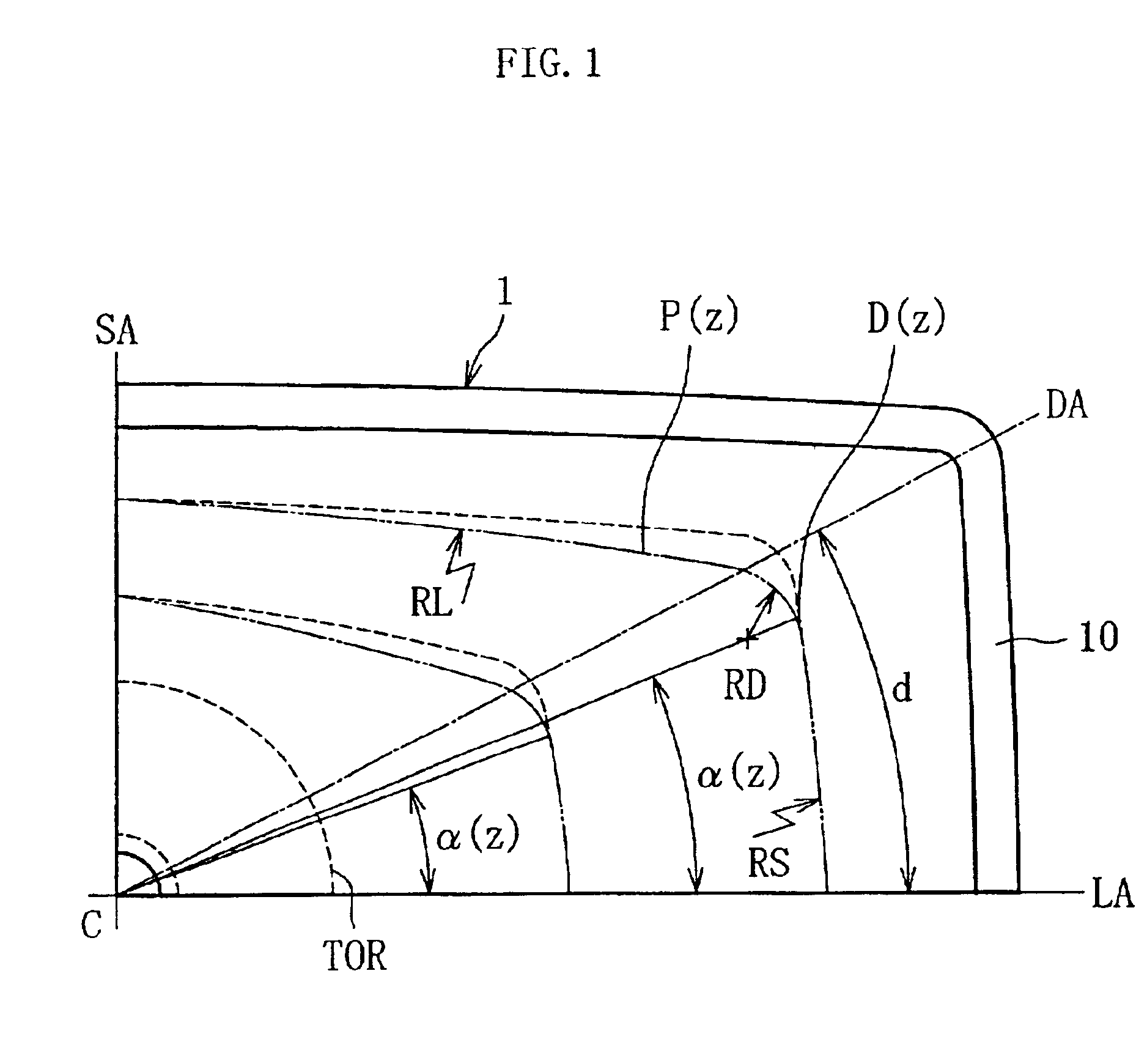
The following section describes an embodiment of a funnel for a cathode ray tube (size: 76 cm, aspect ratio: 16:9, deflection angle: 120°, and neck outside diameter: 29.1 mm) based on FIG. 1 to FIG. 4. Constitution elements common to those in FIG. 6 through FIG. 8 are given the same numerals and detailed description for them is omitted in the following description.

FIG. 1 is the first quadrant of a front view of a funnel for a cathode ray tube according to an embodiment. A chain double-dashed line shows a contour of an outer surface on a cross section P(z) of the embodiment. A dashed line shows a contour of an outer surface on the cross section of a conventional funnel for a cathode ray tube. For example, values of three arcs RL, RD, and RS at z=60 (mm) are RL=4072 mm, RD=40 mm, and RS=636 mm for the contour of the outer surface of the conventional funnel represented as the dashed line, and RL=1459 mm, RD=40 mm, and RS=933 mm for the contour of the outer surface of the embodiment rep...


PUM


Abstract

A funnel for a cathode ray tube has a relationship 0<α(z)<d in an arbitrary cross section P(z) parallel with a plane including an open end portion, where α(z) is an angle (°) defined between a line and a major axis (LA) of the funnel, the line being connecting an outermost part D(z) on at least one of an outer surface and an inner surface of the body portion and a center axis (C) of the funnel, and d is an angle (°) defined between a diagonal axis (DA) of the funnel and the major axis (LA).

Description

BACKGROUND OF THE INVENTIONThe present invention relates to a funnel constituting a glass bulb for a cathode ray tube.The glass bulb for a cathode ray tube comprises a front panel on which an image is displayed, and a rear funnel which is sealed to the panel for forming a glass envelope. As shown in FIG. 6, the funnel 1 comprises an open end portion 10 in an approximately rectangular shape similar to the panel, a neck portion 11 in a cylindrical shape for mounting an electron gun, a yoke portion 12 on which a deflection coil is externally mounted, and a body portion 13 in a funnel-shape which gradually changes in a direction from the open end portion 10 to the yoke portion 12. The joint portion between the yoke portion 12 and the body portion 13 is generally called TOR (Top Of Round).The contour of a cross section P(z) of the body portion 13 in parallel with the open end portion 10 is a rectangle similar to the open end portion 10 in the vicinity of the open end portion 10 (z=0), an...

Claims


Application Information

Patent Timeline
Patent Type & Authority Patents(United States)
IPC IPC(8): H01J29/86H01J29/02
CPCH01J29/861H01J2229/8616H01J29/02
Inventor KAKIGI, HIROSHI
Owner NIPPON ELECTRIC GLASS CO LTD
Why Eureka
Try Eureka