
High voltage-wide band amplifier

Inactive Publication Date: 2005-03-01
QORVO US INC
View PDF12 Cites 8 Cited by
  • Summary
  • Abstract
  • Description
  • Claims
  • Application Information

AI Technical Summary

Benefits of technology

The objects, features and advantages of the present invention include providing a wide band high voltage Darlington topology that may (i) integrate common-base transistors within a Darlington pair to achieve improved breakdown voltage, thermal stability, and / or bandwidth compared with conventional approaches, (ii) implement a low impedance voltage reference to the common-base transistor(s) to improve breakdown voltage of the transistor(s), (iii) implement a cascoded Darlington pair having a wideband feedback amplifier configured to drive high voltage optical modulator devices, and / or (iv) integrate a cascode Darlington pair with an existing Darlington pair for improving breakdown voltage, thermal stability, and / or bandwidth compared with conventional approaches.

Problems solved by technology

However, high speed technologies are typically characterized by low device breakdown voltages.
For high speed SiGe or InP HBT processes, the breakdown voltage BVceo tends to be low which can limit implementation in broadband laser modulator driver applications, for example.

Method used


Image

  • High voltage-wide band amplifier
  • High voltage-wide band amplifier
  • High voltage-wide band amplifier

Examples


Embodiment Construction

The present invention may integrate common-base transistors within a Darlington pair to improve the overall breakdown voltage, thermal behavior, and / or bandwidth of such a Darlington topology. The present invention may use a low impedance voltage reference to provide the base bias of the common-base transistors. Such a base bias may increase the Darlington breakdown voltage to a value approaching a breakdown voltage (e.g., Bvcbo) of the common-base transistors.

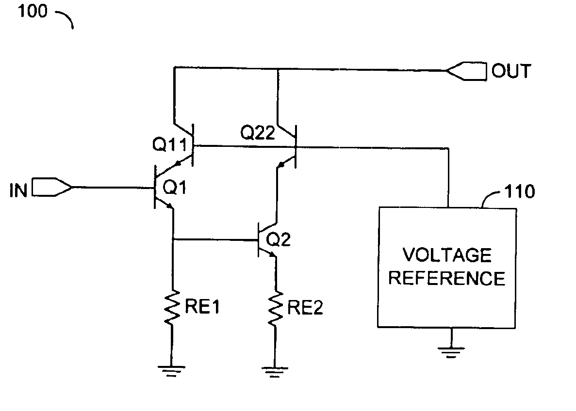
Referring to FIG. 5, a diagram illustrating a circuit 100 implementing a cascode Darlington amplifier in accordance with a preferred embodiment of the present invention is shown. The circuit 100 generally integrates (or couples) common-base transistors (e.g., transistors Q11 and Q22) with a Darlington transistor pair (e.g., transistors Q1 and Q2) to improve overall breakdown voltage, thermal stability and / or bandwidth of the circuit 100 when compared to conventional approaches. Specifically, the transistors Q11 and Q22 share t...


PUM


Abstract

An apparatus comprising a Darlington transistor pair, a first common-base transistor and a second common-base transistor. The Darlington transistor pair may be configured to generate an output signal in response to an input signal. The first common-base transistor may be coupled between the Darlington transistor pair and the output signal. The second common-base transistor may also be coupled between the Darlington transistor pair and the output signal. The first and second common-base transistors may each have a base configured to receive a reference voltage.

Description

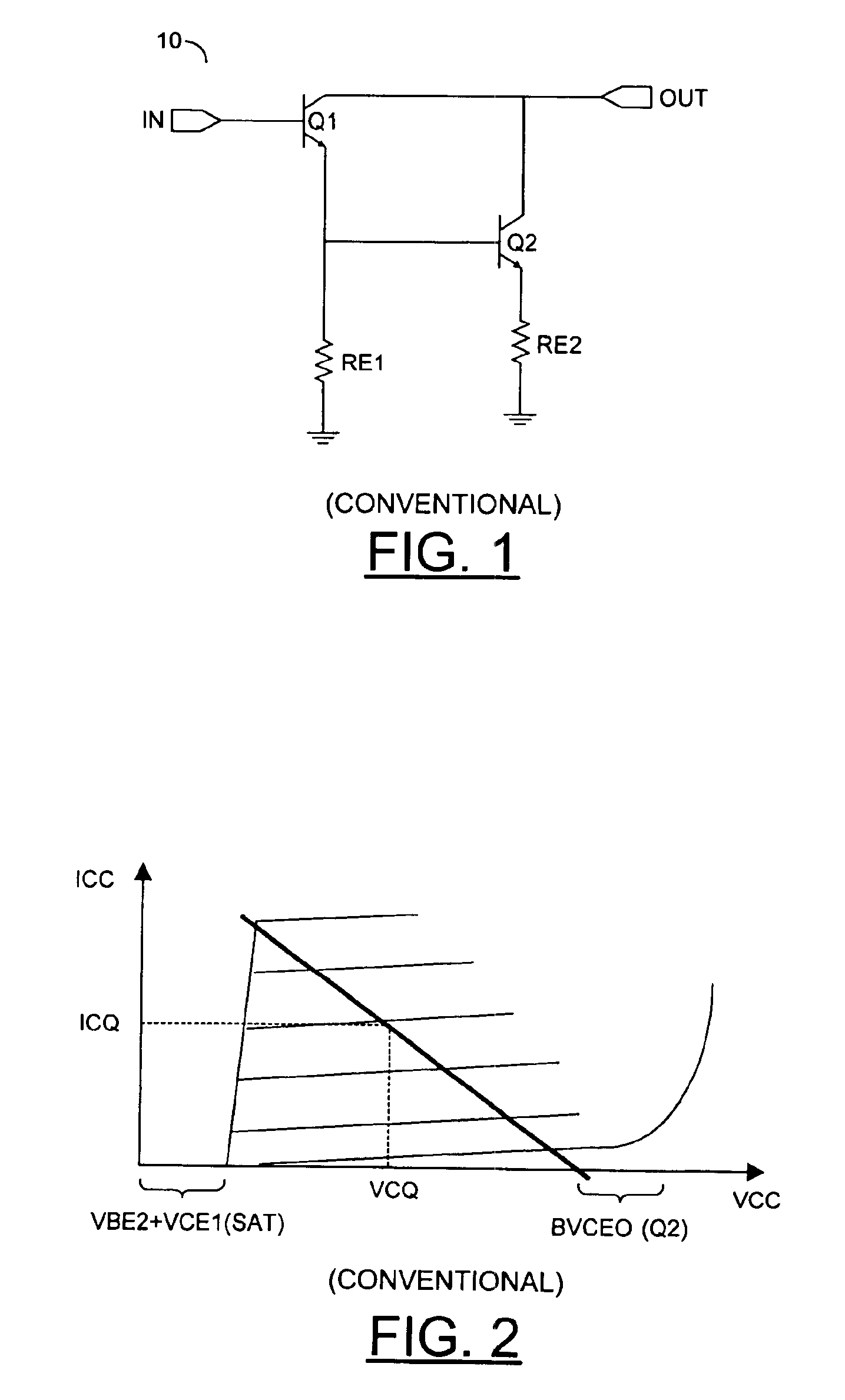
FIELD OF THE INVENTIONThe present invention relates to amplifiers generally and, more particularly, to a method and / or architecture for implementing a high voltage-wide band amplifier.BACKGROUND OF THE INVENTIONMulti-decade high voltage driver amplifiers are needed for both cable-television (i.e., 10 MHz-1.2 Ghz) and SONET 12.5 Gb / s OC-192 optical modulator transmitter applications. Wide bandwidth and high output voltage operation is achieved by combining broad band circuit topologies such as distributed and Darlington feedback amplifiers with a high speed technology such as SiGe or InP heterojunction bipolar transistors (HBTs). However, high speed technologies are typically characterized by low device breakdown voltages.In order to satisfy the need for wide bandwidth and high voltage output, conventional approaches often implement a Darlington amplifier pair. A Darlington pair can increase the bandwidth of a traditional common-emitter feedback amplifier by replacing the common-emit...

Claims


Application Information

Patent Timeline
IPC IPC(8): H03F3/189H03F3/19
CPCH03F3/19
Inventor KOBAYASHI, KEVIN W.
Owner QORVO US INC
Learn More