
Double winding twin coil for thin-film head writer

a twin coil and writer technology, applied in the field of data storage systems, can solve the problems of damage to the write pole, damage to the coil, and itself is a difficult task to achieve, and achieve the effects of reducing the insulation spacing, enhancing the coil design, and small yoke length

Inactive Publication Date: 2005-03-01
WESTERN DIGITAL TECH INC
View PDF11 Cites 161 Cited by
  • Summary
  • Abstract
  • Description
  • Claims
  • Application Information

AI Technical Summary

Benefits of technology

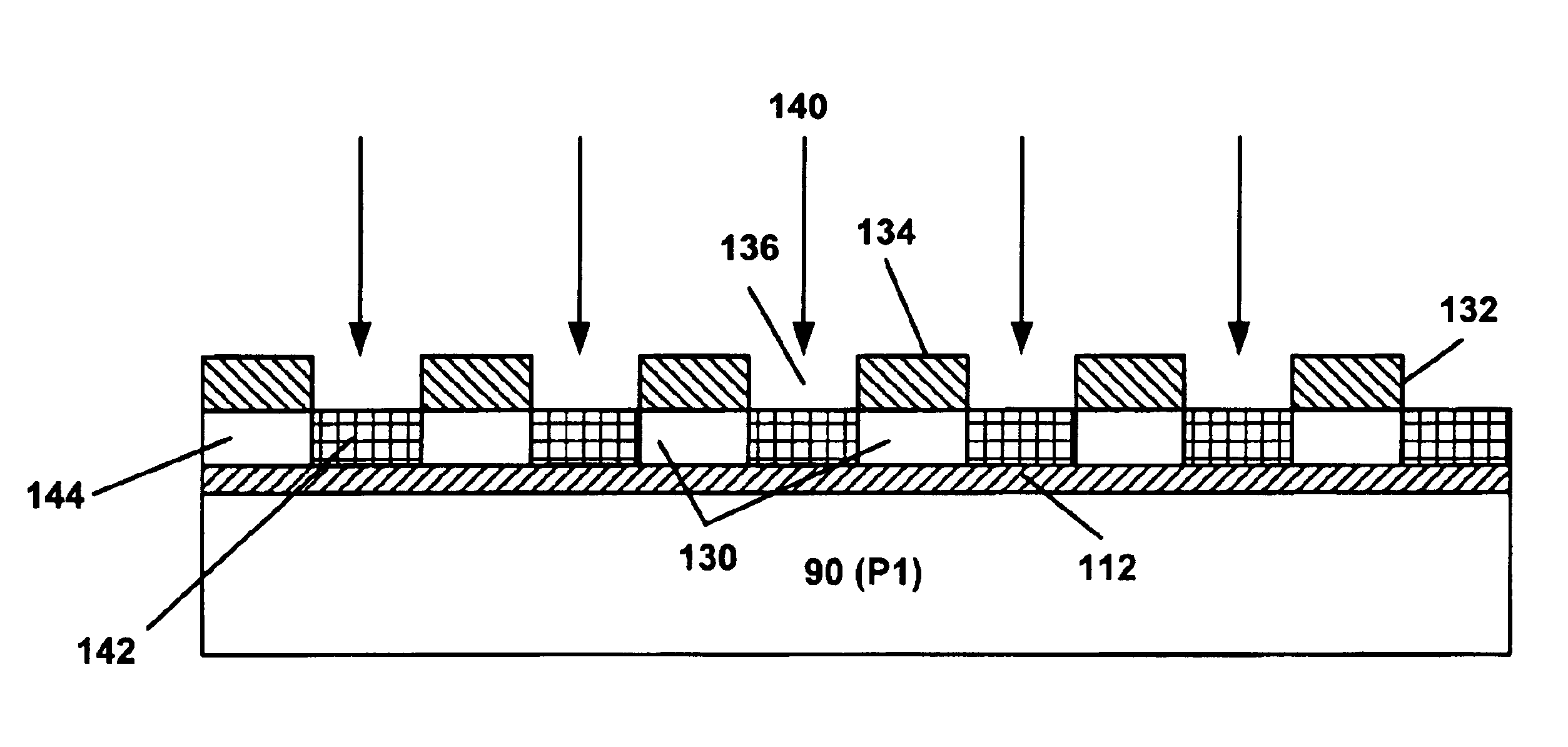
It is a feature of the present invention to present a new enhanced inductive coil design for use in data storage magnetic disk drives with areal density over 35 Gb / in2. The enhanced inductive coil design of the present invention features a double wound twin coil concept using the following process:1. The twin coil is built on the same layer with a demesne process.2. A tri-level process is implemented in the layout of the first coil to ensure that the coil width and spacing are uniform and even, in order for the second coil to be wound therebetween.3. A conformal dielectric layer of approximately 0.1 to 0.2 μm in thickness is deposited between the two coils to serve as insulation.4. The coils are formed by a copper (Cu) seed layer plating process which eliminates the potential damage to the coils during production.
Using the enhanced process of the present invention, the new coil design is able to achieve a smaller yoke length of 15 μm or less while maintaining at least the same number of coils per turn as a result of the reduction in the insulation spacing between the two coils. A further advantage of the enhanced coil design of the present invention is the improved reliability by reducing the electrical shorting possibility realized by the seed layer ion milling process.

Problems solved by technology

The inductive coil process according to the Takahashi patent presents a number of disadvantages that significantly offset the benefit of high areal density of the conventional coil design.
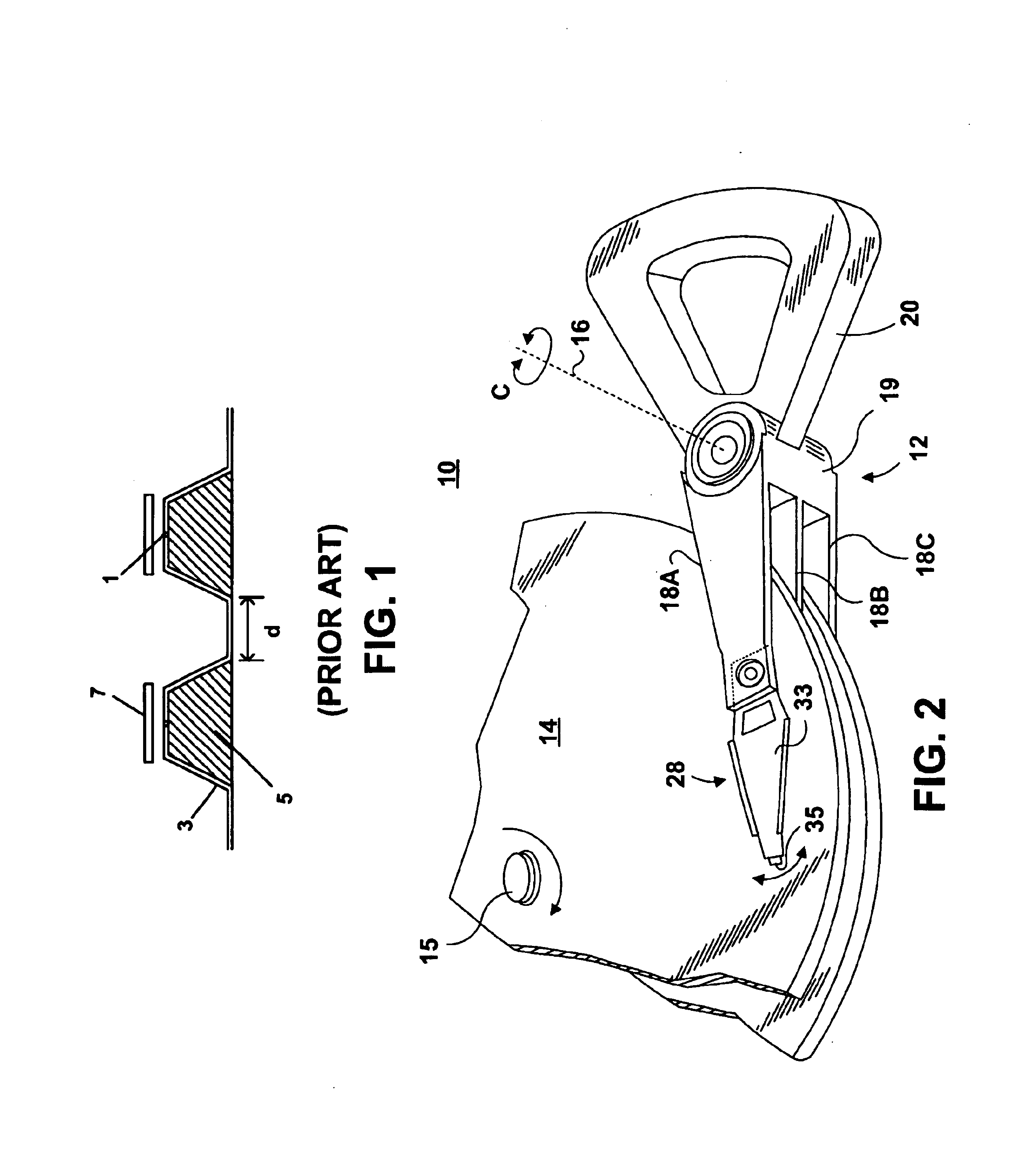
Thus, during the wet etch process which is designed to remove the exposed photo resist material, the etching solution may seep through the pin holes 1 in the dielectric layer 3 to permeate into the underlying conductor surface 5, thereby likely resulting in a damage to the coil.
In some instances, the etching solution may penetrate far enough to cause damage to the write pole P1.
As a consequence, a considerable endeavor is required to ensure that the dielectric layer is free of pinholes 1, which in itself is a difficult task to accomplish.
Yet another disadvantage with the Takahashi design is the coil size limitation due to the alignment process and the physical limitation of the photo resist.
As the demand for high coil density increases, the coil size becomes smaller and so does the gap width “d.” As a result, the alignment becomes more challenging, resulting in a potential misalignment which could adversely affect the quality and production of the conventional inductive coils.
Furthermore, the photo resist typically reaches a physical limitation of about 0.2 μm.
Thus, both the alignment problem and the photo resist limitation impose a size constraint on the conventional inductive coil.
As a result, conventional inductive coils as exemplified by the Takahashi patent, may not be further enhanced beyond their maximum limit as dictated by the foregoing size constraint, thus preventing these coils from meeting the demand for greater areal density in high capacity disk drives.
Currently, a conventional coil design may have reached its size limitation of 17 μm with a coil density of 9 turns per coil.

Method used


Image

  • Double winding twin coil for thin-film head writer
  • Double winding twin coil for thin-film head writer
  • Double winding twin coil for thin-film head writer

Examples


Embodiment Construction

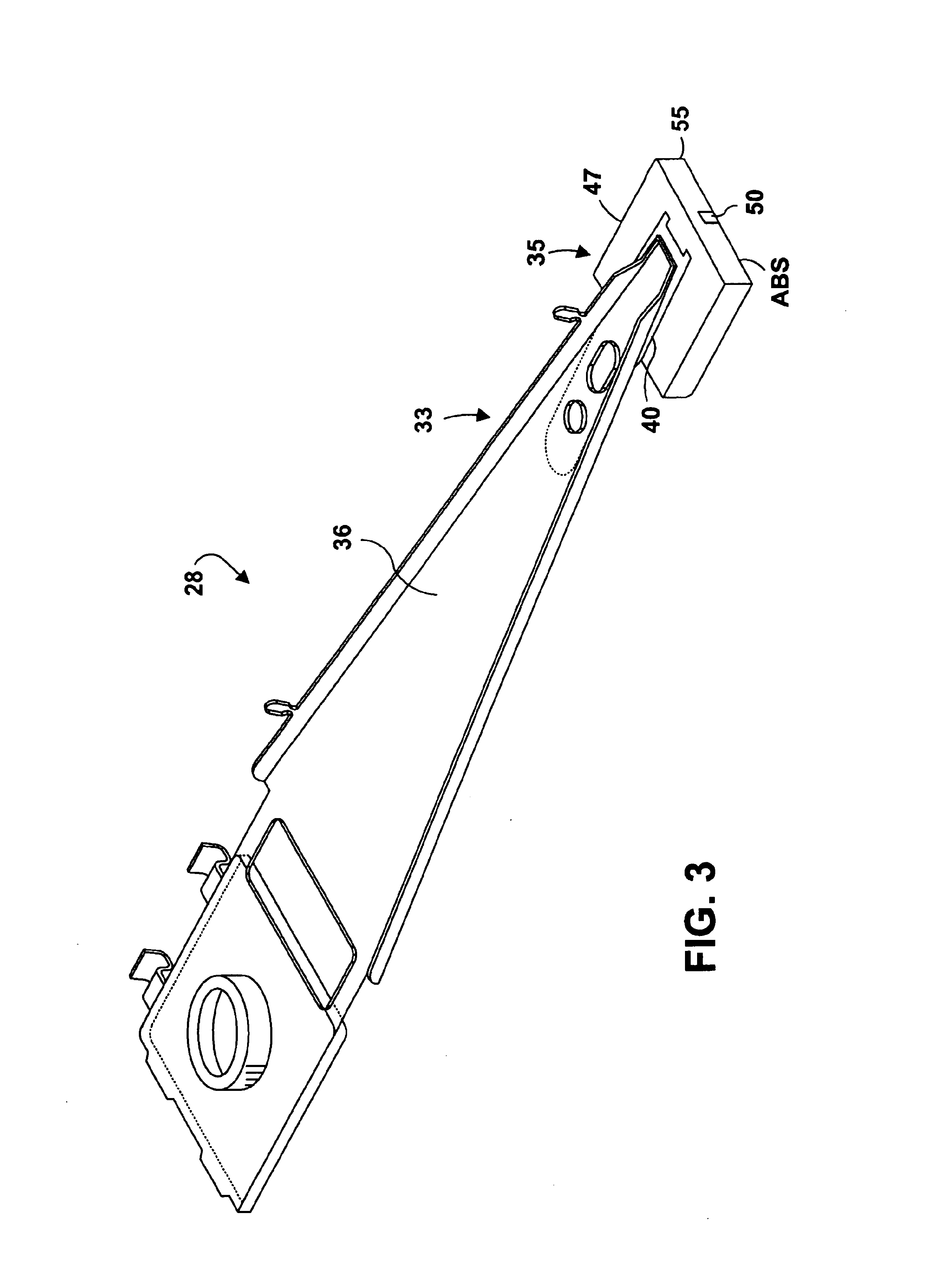
FIG. 2 illustrates a disk drive 10 comprised of a head stack assembly 12 and a stack of spaced apart magnetic data storage disks or media 14 that rotate about a common shaft 15. The head stack assembly 12 is pivoted about an actuator axis 16 in the direction of the arrow C. The head stack assembly 12 includes a number of actuator arms, only three of which 18A, 18B, 18C are illustrated, which extend into spacings between the disks 14.

The head stack assembly 12 further includes an E-shaped block 19 and a magnetic rotor 20 attached to the block 19 in a position diametrically opposite to the actuator arms 18A, 18B, 18C. The rotor 20 cooperates with a stator (not shown) for rotating in an arc about the actuator axis 16. Energizing a coil of the rotor 20 with a direct current in one polarity or the reverse polarity causes the head stack assembly 12, including the actuator arms 18A, 18B, 18C, to rotate about the actuator axis 16 in a direction substantially radial to the disks 14.

A head gi...


PUM

PropertyMeasurementUnit
widthaaaaaaaaaa
widthaaaaaaaaaa
sizeaaaaaaaaaa

Abstract

An enhanced inductive coil design for use in data storage magnetic disk drives with areal density over 35 Gb / in2, features a double wound twin coil that is able to achieve a yoke length of 15 μm or less by reducing the insulation spacing between the two coils. The coil further presents improved reliability by reducing the possibility of occurrence of electrical shorting. The coil is made by forming two interleafing conductors on the same layer with a demesne process. A tri-level process is implemented in the layout of the first conductor to ensure that the coil width and spacing are uniform and even, in order for the second conductor to be wound therebetween. A conformal dielectric layer of approximately 0.1 to 0.2 μm in thickness is deposited between the two conductors and serves as insulation. The two conductors are formed by a copper seed layer plating process that eliminates potential damage to the conductors during production.

Description

FIELD OF THE INVENTIONThe present invention relates in general to data storage systems such as disk drives, and it particularly relates to a thin film read / write head for use in such data storage systems. More specifically, the present invention relates to an advanced inductive coil design and manufacturing process for thin film heads. The new inductive coil design features a double wound twin coil having a shorter yoke length relative to a conventional design while maintaining at least the same number of coil turns. The new coil design and process enable the disk drive to achieve a greater areal density, hence greater storage capacity than a conventional coil design.BACKGROUND OF THE INVENTIONIn a conventional magnetic storage system, a thin film magnetic head includes an inductive read / write transducer mounted on a slider. The thin film head is coupled to a rotary actuator magnet and a voice coil assembly by a suspension and an actuator arm positioned over a surface of a spinning ...

Claims


Application Information

Patent Timeline
Patent Type & Authority Patents(United States)
IPC IPC(8): G11B5/31H01F5/00
CPCG11B5/3116H01F5/003
Inventor FENG, AIGUORAFFERTY, DENNISXIONG, WEIHUAI, YIMING
Owner WESTERN DIGITAL TECH INC
Learn More