
Network receiver utilizing pre-determined stored equalizer coefficients

a network receiver and equalizer technology, applied in the field of network interfacing, can solve the problems of high-speed and costly digital signal processing circuits, inability to calculate the coefficients of up to 44 11-bit frames, and inability to achieve the effect of reducing the number of frames

Inactive Publication Date: 2005-03-01
ADVANCED MICRO DEVICES INC
View PDF3 Cites 52 Cited by
  • Summary
  • Abstract
  • Description
  • Claims
  • Application Information

AI Technical Summary

Benefits of technology

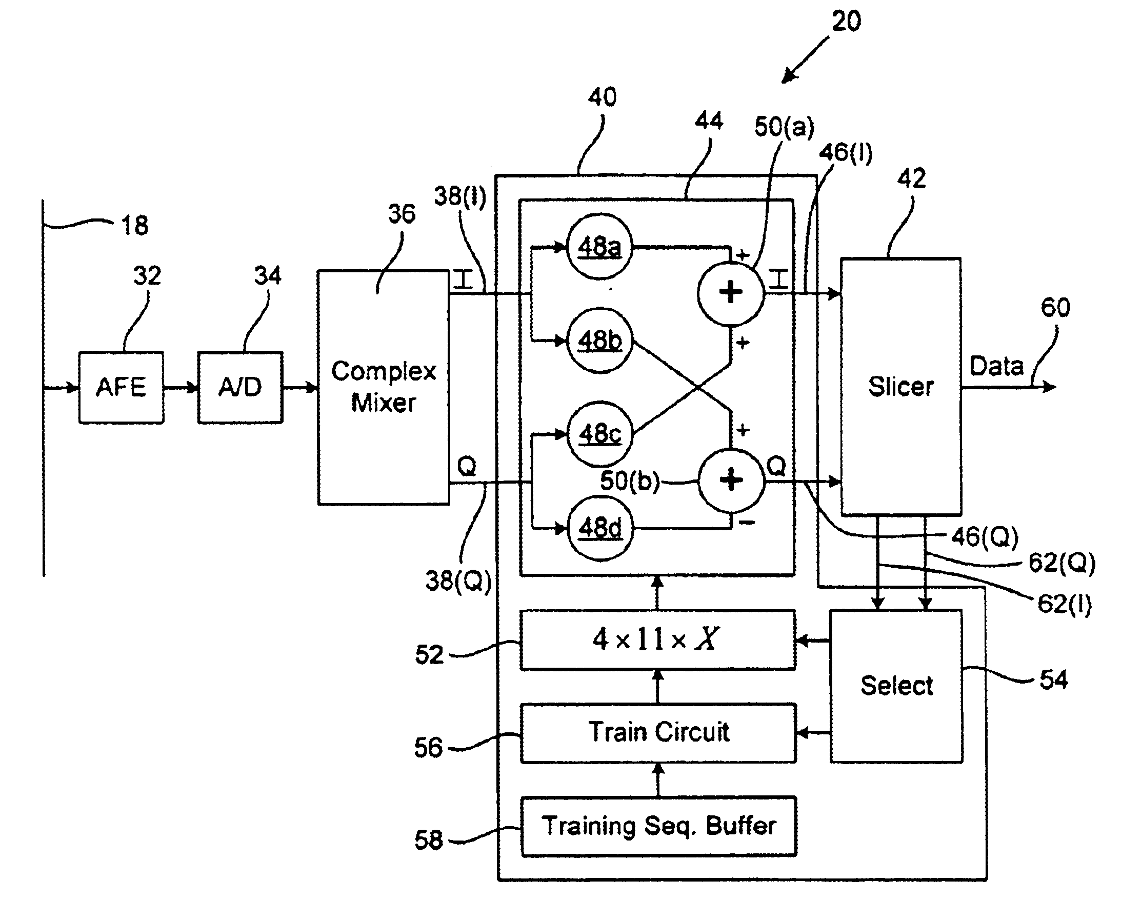
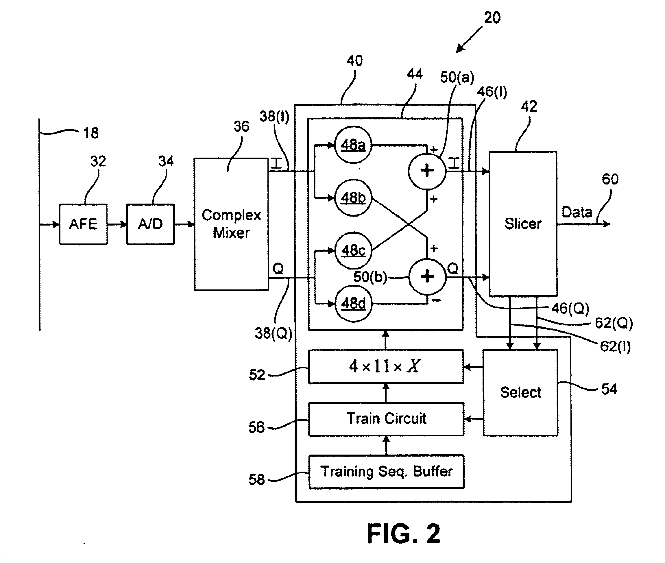
The method may further include: d) slicing the equalized digital carrier signal by mapping the digital carrier signal to a plurality of defined constellation points to recover the transmitted data; and e) providing the equalizer with an error signal representing the distortion between the equalized carrier signal and the defined constellation points. Further yet, the error signal may be utilized to select the set of coefficients providing minimal error during a frame training sequence in which a predetermined bit sequence is transmitted.

Problems solved by technology

However, the network topology tends to distort the high frequency carrier signal due to numerous branch connections and different lengths of such branches causing numerous reflections of the transmitted carrier.
Such problems are even more apparent in a network which uses home telephone wiring cables as the network cable medium because the numerous branches and connections are typically designed for transmission of plain old telephone system POTS signals in the 0.3-3.4 kilohertz frequency range and are not designed for transmission of high frequency carrier signals on the order of 7 Megahertz.
A problem associated with such receivers is that coefficient calculation circuitry needed for calculating upward of 44 11-bit coefficients within the short duration of the training period of a frame can require upward of 2.7 billion operations per second.
This requires high-speed and costly digital signal processing circuits.
Such circuits consume substantial amount of power and are relatively expensive.
As a result, such circuits are not practical in battery powered devices for power consumption reasons, and are unsuitable for inexpensive consumer network devices such as smoke detectors, door openers and other devices requiring inexpensive network access.

Method used


Image

  • Network receiver utilizing pre-determined stored equalizer coefficients
  • Network receiver utilizing pre-determined stored equalizer coefficients
  • Network receiver utilizing pre-determined stored equalizer coefficients

Examples


Embodiment Construction

The present invention will now be described in detail with reference to the drawings. In the drawings, like reference numerals are used to refer to like elements throughout.

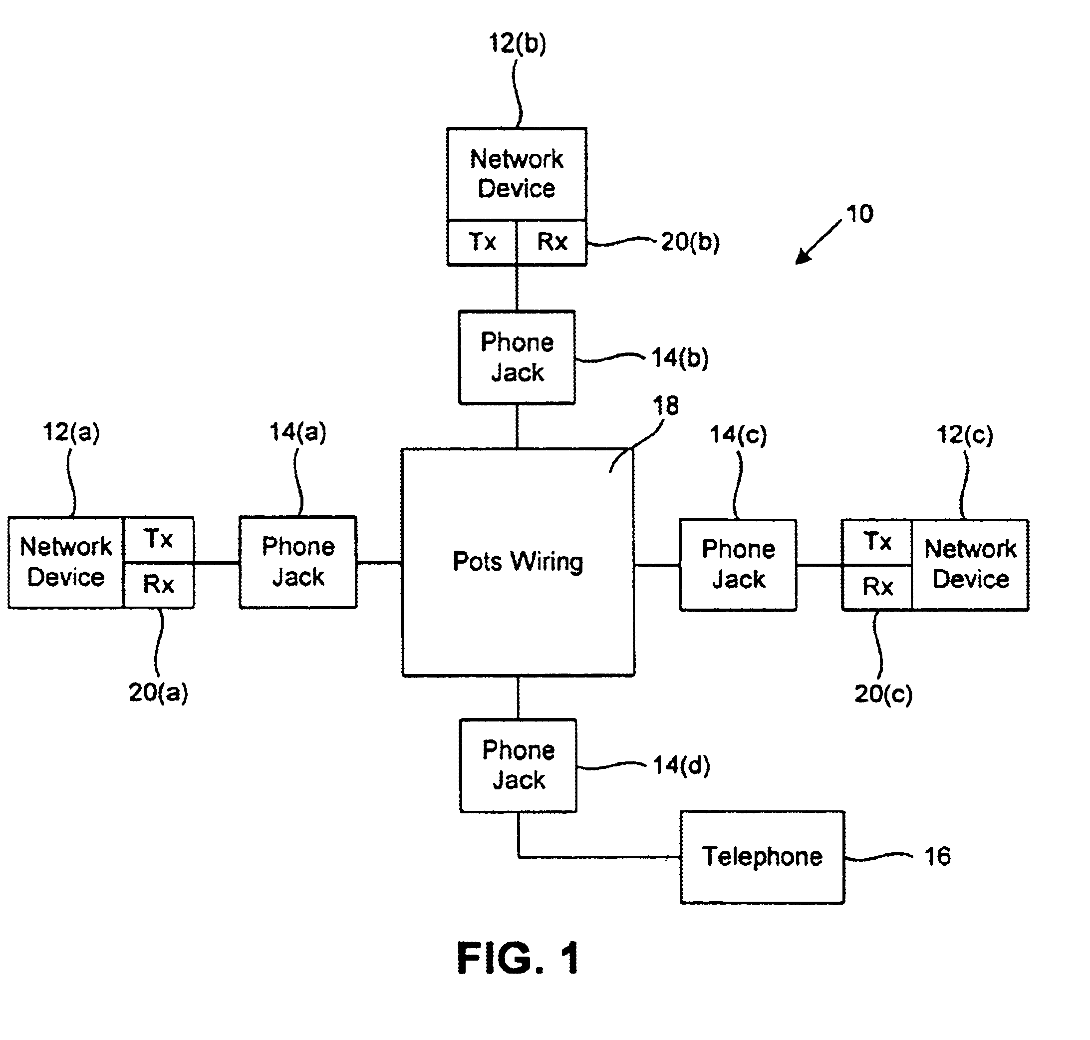
FIG. 1 is a diagram of a local area network 10 implemented in a home environment using twisted pair network media according to an embodiment of this invention. As shown in FIG. 1, the network 10 includes network stations 12(a)-12(c) that are connected to a telephone line (twisted pair) wiring 18 via RJ-11 phone jacks 14(a)-14(c) respectively. A telephone 16 is connected to an RJ-11 phone jack 14(d) and may continue to make telephone calls while network devices 12(a)-12(c) are communicating network data.

Each network device 12 may be a personal computer, printer, server, or other intelligent consumer device such as a smoke detector, appliance, door opener or other small electric device. Each of network devices 12(a)-12(c) communicates by transmitting a frame of data built upon analog network carrier signal modulate...


PUM


Abstract

A network receiver is configured for receiving a modulated carrier signal representing a data frame from a network transmitter via a network medium, the receiver includes an adaptive equalizer with a finite impulse response filter for filtering the received signal. The filter utilizes a plurality filter coefficients. A cache stores a plurality of sets of coefficients for use by the filter and the equalizer selects a set of coefficients for receiving the data frame.

Description

TECHNICAL FIELDThe present invention relates generally to network interfacing, and more particularly, to a network receiver which utilizes pre-determined stored equalizer coefficients for recovering transmitted data.BACKGROUND OF THE INVENTIONThe transmission of various types of digital data between computers continues to grow in importance. The predominant method of transmitting such digital data includes coding the digital data into a low frequency base data signal and modulating the base data signal onto a high frequency carrier signal. The high frequency carrier signal is then transmitted across a network cable medium, via RF signal, modulated illumination, or other network medium, to a remote computing station.At the remote computing station, the high frequency carrier signal must be received and demodulated to recover the original base data signal. In the absence of any distortion of the carrier signal across the network medium, the received carrier would be identical in phase...

Claims


Application Information

Patent Timeline
IPC IPC(8): H04L25/03
CPCH04L25/03133H04L2025/0377H04L2025/03477
Inventor GARG, ATULNAYLER, COLIN D.
Owner ADVANCED MICRO DEVICES INC
Learn More