Apparatus, method and system of liquid-based, wide range, fast response temperature control of electric devices

a technology of electric devices and liquid-based devices, applied in the field of temperature control systems, can solve the problems of increasing difficult to maintain the chip temperature near a constant set point, and difficult to adjust the temperature error between the desired and actual temperature, etc., to achieve the effect of small form factor and flexibility in chip situations, fast response and fast set point temperature chang

Inactive Publication Date: 2005-03-01
DELTA DESIGN
View PDF52 Cites 37 Cited by
  • Summary
  • Abstract
  • Description
  • Claims
  • Application Information

AI Technical Summary

Benefits of technology

The present invention provides a liquid based, wide range, fast response chip temperature control system. The wide temperature range is achieved by extending the effective temperature range of a liquid based coolant loop with resistive heating in the control surface. In this way, the desired temperature range for testing chips can be achieved, while supplying the features of: (i) fast set point temperature change, (ii) response to instantaneous power dissipation changes, and (iii) small form factor and flexibility in chip situations.

Problems solved by technology

But if the instantaneous power dissipation of the chip varies up and down in a wide range while operating or testing, then maintaining the chip temperature near a constant set point is very difficult.
Combining the ability to force temperature across a wide temperature range, while accommodating the temperature changes associated with varying instantaneous power dissipation, is very challenging.
As the nominal power density of the chips continue to increase, the ability of forced air convection systems to overcool reaches practical limits, causing increases in the temperature error between the desired and actual temperatures relative to set point.
Another problem is that chips fabricated in the latest processes have an increased sensitivity to high temperatures.
The potential for chip damage due to overheating adds risk to the use of the overheating approach.
Increased time to set point is the result, with lost utilization of expensive test equipment and engineering personnel as an expense.
This imposes mechanical packaging constraints which limit the flexibility to bring the surface of the temperature forcing system control surface into contact with the chip or chip package.
This also causes increased error between the desired and actual temperatures.

Method used


Image

  • Apparatus, method and system of liquid-based, wide range, fast response temperature control of electric devices
  • Apparatus, method and system of liquid-based, wide range, fast response temperature control of electric devices
  • Apparatus, method and system of liquid-based, wide range, fast response temperature control of electric devices

Examples


examples

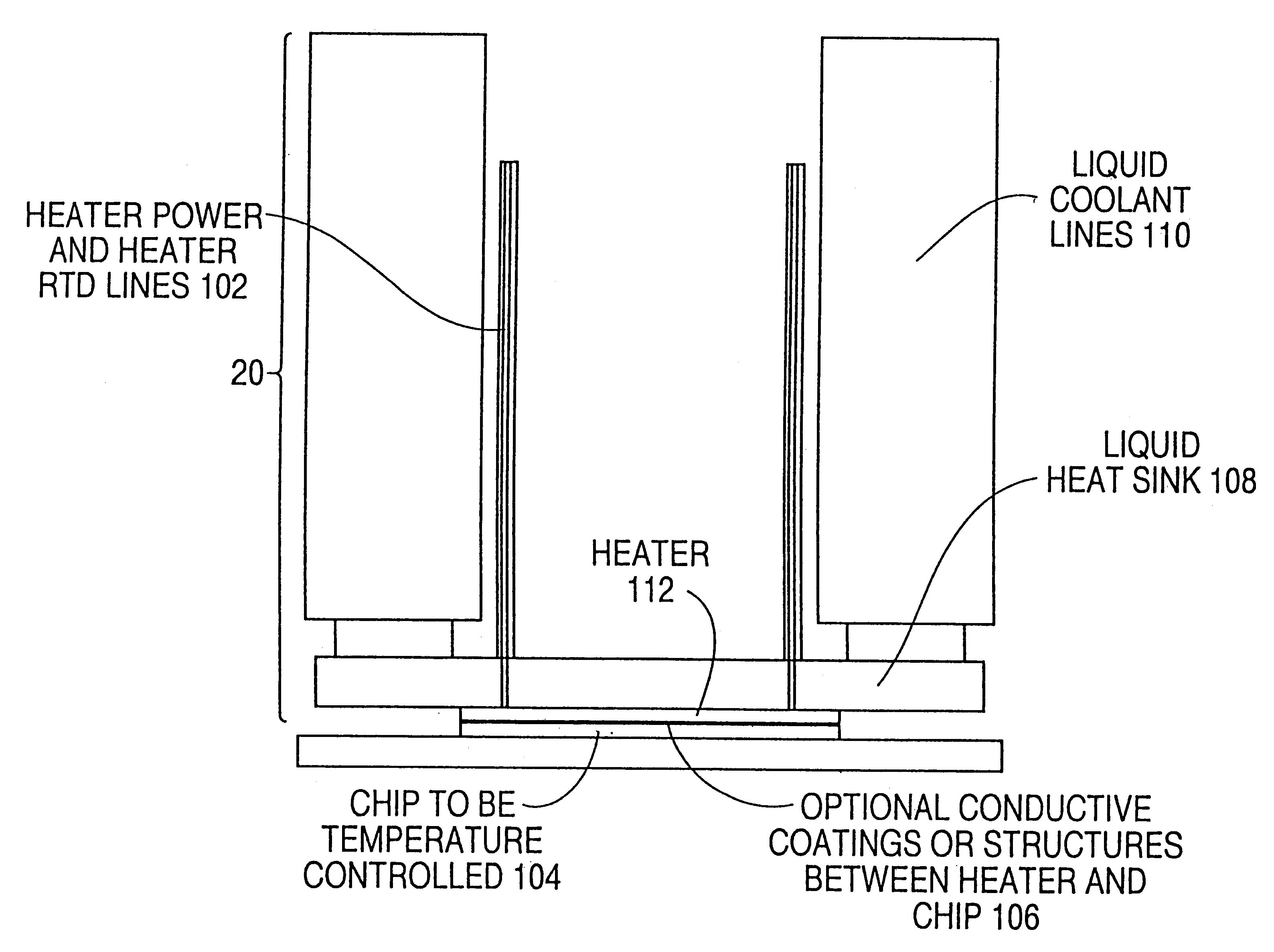
One present embodiment uses HFE7100 as the liquid coolant, operating in the temperature range of −40.degree. C. to +40.degree. C. The temperature difference between the coolant supply and the chip set point temperature ranges between 5.degree. C. and 160.degree. C. The high temperature is limited by long term reliability issues associated with rapid, large, repeated temperature variations and associated thermal stresses of the coolant loop and the heater / heat exchanger assembly. It is also limited by the maximum set point to average liquid temperature difference sustainable with the power rating of the heater power supply. It is also limited by the materials and processes used to manufacture the heater / heat exchanger assembly, such as the breakdown temperature of an epoxy, the melting point of a solder, or the boiling point of a coolant. The current system calls for a chip set point temperature range of −35.degree. C. to +125.degree. C. This would require at least an 85 degree C. De...

second embodiment

A second embodiment uses water or a water / glycol (antifreeze) or water / methanol mixture, operating in the temperature range of +10.degree. C. to +90.degree. C. The temperature difference between the liquid and the chip set point temperature can range between 5.degree. C. and 160.degree. C. The chip set point temperature ranges between +15.degree. C. to +170.degree. C.

Another embodiment has a chiller temperature range of −40 degrees C. to 50 degrees C. The set point temperature is specified at 0 degrees C. to 110 degrees C. It can use the heater for active control, to compensate for self-heating of the DUT, from 40 degrees C. to 10 degrees C. The performance of the active control will degrade as the set point temperature approaches the coolant temperature. The amount of the degradation depends on the package type and the power density, among other things. Degradation is displayed in an increased die temperature deviation.

4. Variations

A heat exchanger may have many other implementatio...


PUM


Abstract

An active temperature control system for a DUT utilizes a heat sink containing HFE7100 liquid and an electric heater. The liquid is cooled below the set point and the heater is used to bring the DUT up to the set point. Set points in the range of −10 degrees C. to +110 degrees C. can be achieved. The heat sink utilizes only a single coolant for all of the set points, allowing set points to be changed within a few minutes. At a given set point, the heater provides a quick response to offset the effect of self-heating and keep the set point deviation to within a few degrees C. Power following techniques can be utilized to achieve the quick response.

Description

BACKGROUND OF THE INVENTION1. Field of the InventionThis invention relates to temperature control systems which maintain the temperature of an electronic device near a given set point temperature(s) while the device is being operated or tested. Two specific examples of electronic devices which need to be operated or tested at a constant temperature are packaged integrated chips and unpackaged bare chips.2. Description of the Related ArtMaintaining the chip temperature near a given set point is not difficult if the power dissipation of the chip is constant or varies in a small range while operating or testing. In such cases, it is only necessary to couple the chip through a fixed thermal resistance to a thermal mass which is at a fixed temperature. But if the instantaneous power dissipation of the chip varies up and down in a wide range while operating or testing, then maintaining the chip temperature near a constant set point is very difficult. When chips are being debugged or teste...

Claims


Application Information

Patent Timeline
Patent Type & Authority Patents(United States)
IPC IPC(8): G01R31/28G01R31/26
CPCG01R31/2891G01R31/2874G01R31/2806G01R31/2862G05D23/00
Inventor MALINOSKI, MARK F.JONES, THOMAS P.ANNIS, BRIANTURNER, JONATHAN E.
Owner DELTA DESIGN
Why Eureka
Try Eureka