
Filters for engine exhaust particulates

a technology of engine exhaust and filter, applied in the field of particle filters, can solve the problems of inability to accurately predict the amount and type of soot accumulated prior to initiating soot regeneration, and the nature of soot accumulation and combustion behavior of accumulated soot, and achieve the effect of reducing the prospective cost of optimal emissions control systems, maximizing regeneration efficiency, and significantly expanding the range of suitable filter materials and geometries

Inactive Publication Date: 2005-03-08
CORNING INC
View PDF8 Cites 36 Cited by
  • Summary
  • Abstract
  • Description
  • Claims
  • Application Information

AI Technical Summary

Benefits of technology

The present invention provides a method for assessing the regeneration response of engine exhaust particulate filters in a variety of operating conditions. This method involves loading the filter with a controlled amount of combustible particulate material, and monitoring its response during a regeneration cycle. The data collected from these tests can be used to develop models that predict the performance of the filter under different conditions. The invention also includes an apparatus for generating a controlled exhaust gas stream for testing the regeneration response of the filter. These methods can lead to improved understanding and management of filter performance, and can help avoid damage to the filter or inefficient regeneration cycles.

Problems solved by technology

The filters provide excellent filtration of particulate matter, but have experienced problems during the regeneration phase of their operation.
The rate and severity of the exothermic temperatures reached during the filter regeneration reaction can be a problem.
The problem arises in part because the amounts and types of soot accumulated prior to initiating soot regeneration cannot be accurately predicted.
This approach does not take into account the fact that the variety of engine operating conditions that can exist make both the nature of the soot accumulation and the combustion behavior of that accumulated soot highly variable.
This melting leads to failure of the filter due to particulate leakage.
In addition, the extreme nature of some regenerations may induce filter cracking due to the large thermal gradient within the part, also resulting in particulate leakage.
Without knowing the conditions that will damage the filters, engine and engine control designers cannot keep the engine output from creating uncontrolled exothermic reactions during regeneration.
This inability to understand and control the regeneration process to better manage filter performance prevents less costly filter materials from be used to meet the filtration needs of the automotive industry.
Instead expensive materials solutions have to be considered that lead to undesirable tradeoffs in fuel efficiency and emissions
The reason is that it may not always be possible to limit the amount of accumulated soot.
The underlying problem is that present filter regeneration cycles are initiated with limited information about actual filter response, precluding overall design optimization for reduced regeneration cycle frequency and overall reduced system cost.
Much effort has been directed at adapting filter composition and geometry as above described, but little work has been done to understand and control filter response over the wide variations of exhaust input conditions these filters may experience.
While this adaptation has some effect on limiting filter regeneration temperatures, it does not take into account the actual response of the filter to other changes in exhaust gas characteristics.

Method used


Image

  • Filters for engine exhaust particulates
  • Filters for engine exhaust particulates
  • Filters for engine exhaust particulates

Examples


example 1

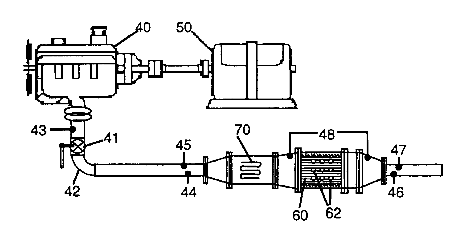
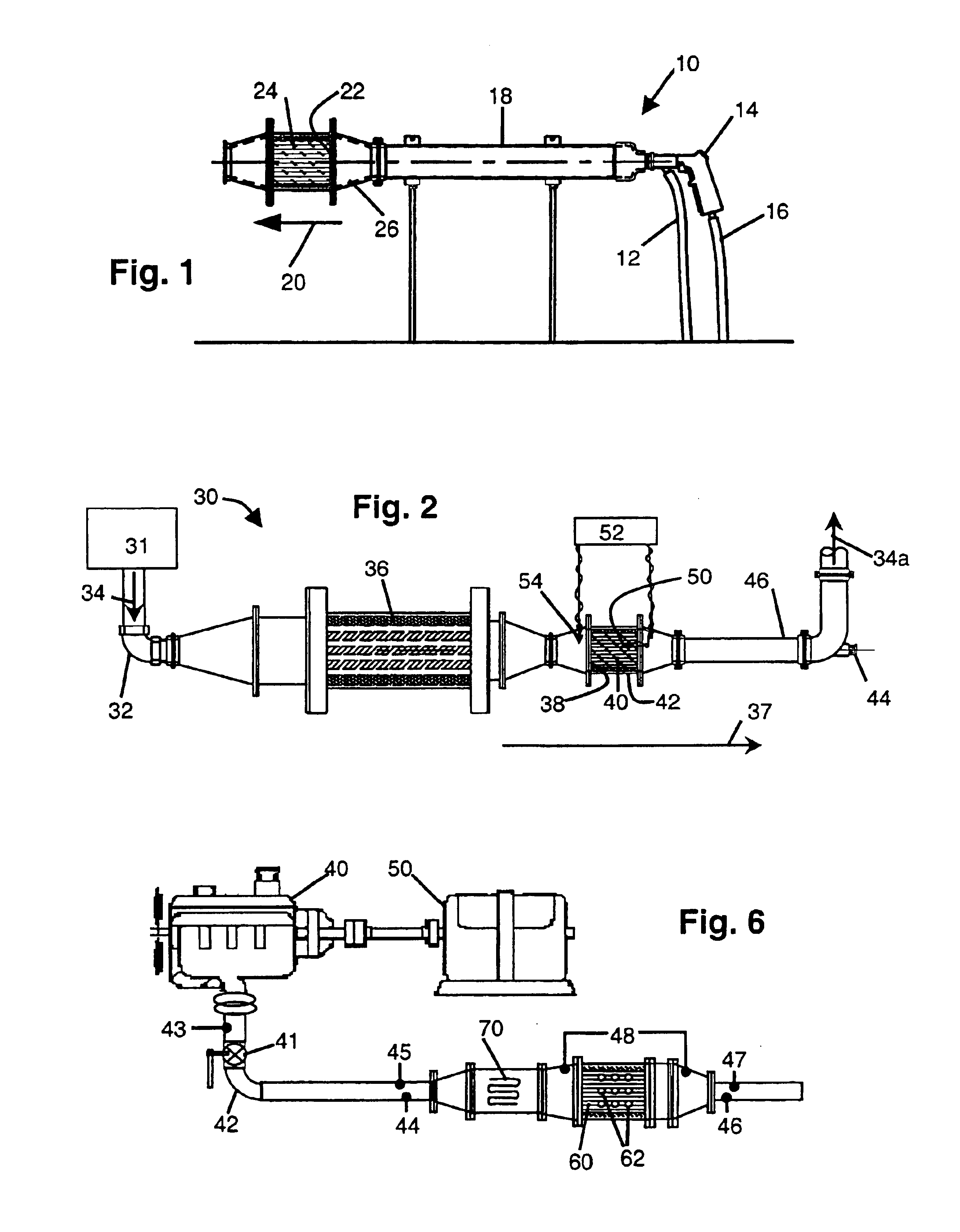
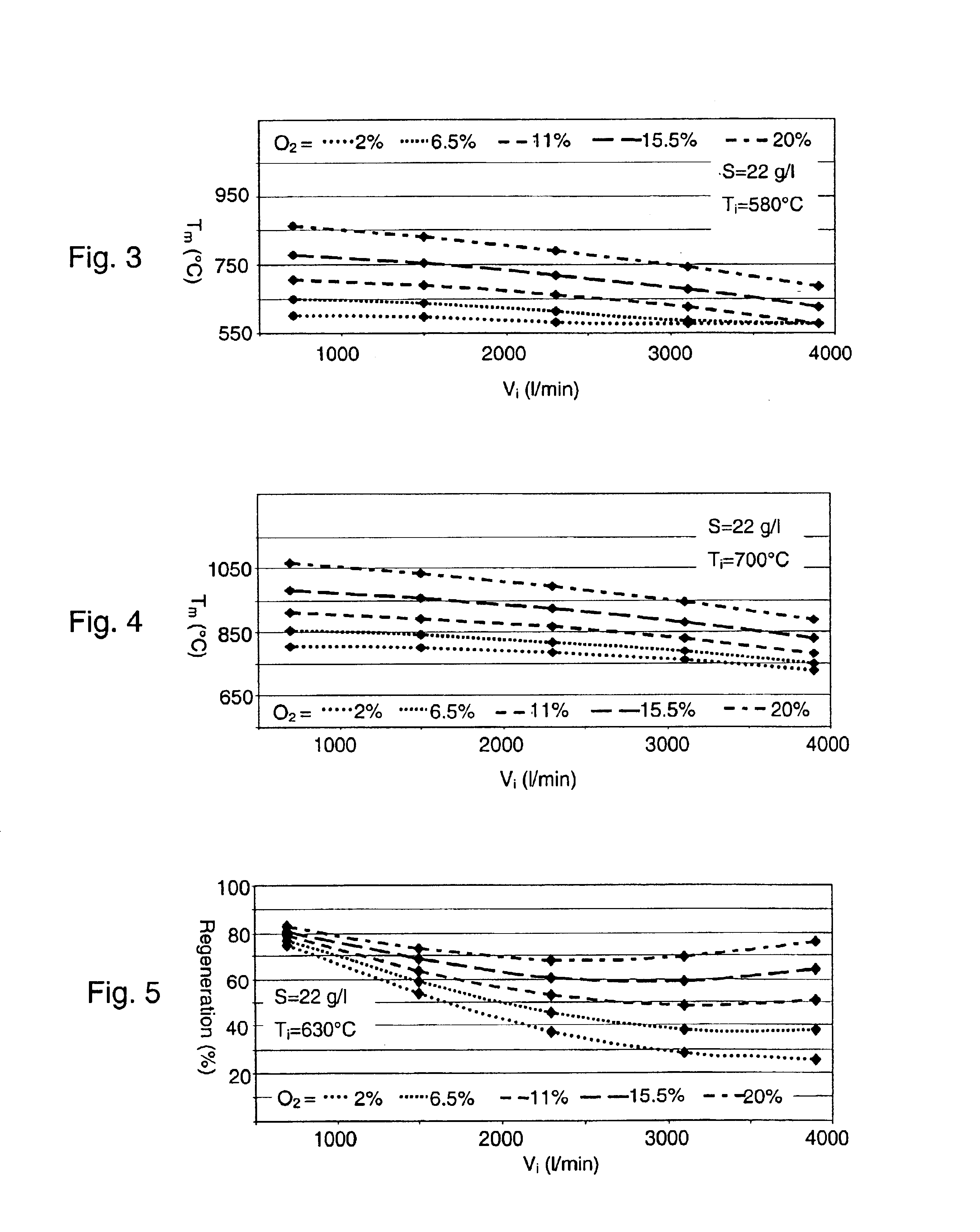
Filter Bench Testing

A porous ceramic wall flow filter of cordierite chemical composition is selected for evaluation. The filter to be evaluated is a cylindrical honeycomb filter of 4.5 inches diameter and 5 inches length, comprising alternately plugged channels at a cell density of 200 cell / in2 of filter frontal area and a channel wall thickness of 0.012 inches, with a wall porosity of 50% volume. This filter configuration is adequate to handle exhaust gas flows such as would be produced by two-liter diesel engines.

For each test run, the selected filter is first preloaded with a measured quantity of an artificial soot, in this case consisting of Printex®-U carbon black from Degussa AG, Frankfurt, Germany. Soot loadings in the range of about 9-22 grams / liter of filter volume are used. The filter is then fitted with a thermocouple for measuring regeneration temperatures, the thermocouple being positioned 4 inches from the filter front face and 10 mm from the outer cylindrical surface ...


PUM

PropertyMeasurementUnit
temperatureaaaaaaaaaa
temperaturesaaaaaaaaaa

Abstract

The regeneration responses of diesel engine exhaust filters are mapped by conducting multiple regeneration runs under controlled conditions of soot loading, exhaust temperature, exhaust flow rate, exhaust oxygen content and / or other regeneration condition variables to generate a multivariate response surface or filter map that can be used to predict regeneration response under other conditions and aid in the design and active management of the filters to improve filter efficiency and extend filter service life.

Description

BACKGROUND OF THE INVENTIONThe present invention relates to particulate filters for the removal of particulates from combustion engine exhaust gases, and methods for using such filters, that provide substantial improvements in filter durability and efficiency.Wall flow diesel particulate filter technology has been used with some success for approximately 15 years. The filters provide excellent filtration of particulate matter, but have experienced problems during the regeneration phase of their operation. The regeneration phase is required to burn the complement of accumulated soot out of the filter. This process is typically accomplished by when the internal temperature of an uncatalyzed filter reaches approximately 600° C. When the carbon soot particles reach this temperature in the presence of adequate oxygen the combustion process can proceed.The rate and severity of the exothermic temperatures reached during the filter regeneration reaction can be a problem. The problem arises ...

Claims


Application Information

Patent Timeline
Patent Type & Authority Patents(United States)
IPC IPC(8): B01D46/44F01N3/023F01N3/021F01N3/027F01N9/00F01N7/00F01N7/02B01D46/00B21K1/70B23P19/06F01N13/02F16B37/06
CPCB01D46/0086B01D46/448B21K1/702F01N3/021F01N13/009F01N3/027F01N9/002F16B37/068F01N3/023B01D2273/18B01D2279/30F01N2240/02F01N2330/06Y02T10/47Y02T10/40
Inventor CRAIG, ANGUS G.LOCKER, ROBERT J.SAWYER, CONSTANCE B.
Owner CORNING INC
Learn More