Ion plating device and ion plating method

a technology of ion plating and ion plating, which is applied in the field of ion plating device and ion plating method, can solve the problems of film damage, achieve the effects of preventing the occurrence of arcing, improving the density and adhesion of the film, and preventing the mixing of impurities

Inactive Publication Date: 2005-03-08
SHIN MEIWA IND CO LTD
View PDF18 Cites 43 Cited by
  • Summary
  • Abstract
  • Description
  • Claims
  • Application Information

AI Technical Summary

Benefits of technology

The present invention has been developed for obviating the above-described problems, and an object of the present invention is to provide an ion plating device and an ion plating method, which prevent occurrence of arcing when using a bias voltage to improve density and adhesion of a film and thereby prevent impurities from being mixed into the film to avoid damage to a substrate and the film.
There is also provided an ion plating device comprising: a vacuum chamber adapted to be evacuated; a substrate holder placed in the vacuum chamber for holding a substrate; and a power supply unit for supplying power used for changing a material of a film to be formed on the substrate into a plasma and depositing the film from the plasma on the substrate to an inside of the vacuum chamber through the substrate holder, wherein the power supply unit is adapted to output a bias voltage composed of a negative bias component having a predetermined negative voltage value for a predetermined output time and a pulse bias component corresponding to a pulse output having a positive voltage value for a predetermined time, with a cycle set in a range of 1 kHz to 1 GHz, and output radio frequency power, further comprising: a function generator for synthesizing a waveform corresponding to the negative bias component of the bias voltage, a waveform corresponding to the pulse bias component of the bias voltage, and a waveform corresponding to radio frequency of the radio frequency power; and a linear amplifier for amplifying the waveform synthesized by the function generator and supplying an amplified waveform. Thereby, filters and hence adjustment of the filters become unnecessary. Also, the output of the bias voltage composed of the negative bias and the pulse bias and the output of radio frequency can be unitarily managed. Consequently, adjustment for well-balanced outputs becomes easy.

Problems solved by technology

For this reason, breakdown of the insulating material occurs, causing arcing.
When a path of the arcing penetrates through the film formed on the substrate 65, the film is damaged.

Method used


Image

  • Ion plating device and ion plating method
  • Ion plating device and ion plating method
  • Ion plating device and ion plating method

Examples


Embodiment Construction

Hereinafter, an embodiment of the present invention will be described with reference to FIGS. 1 through 3.

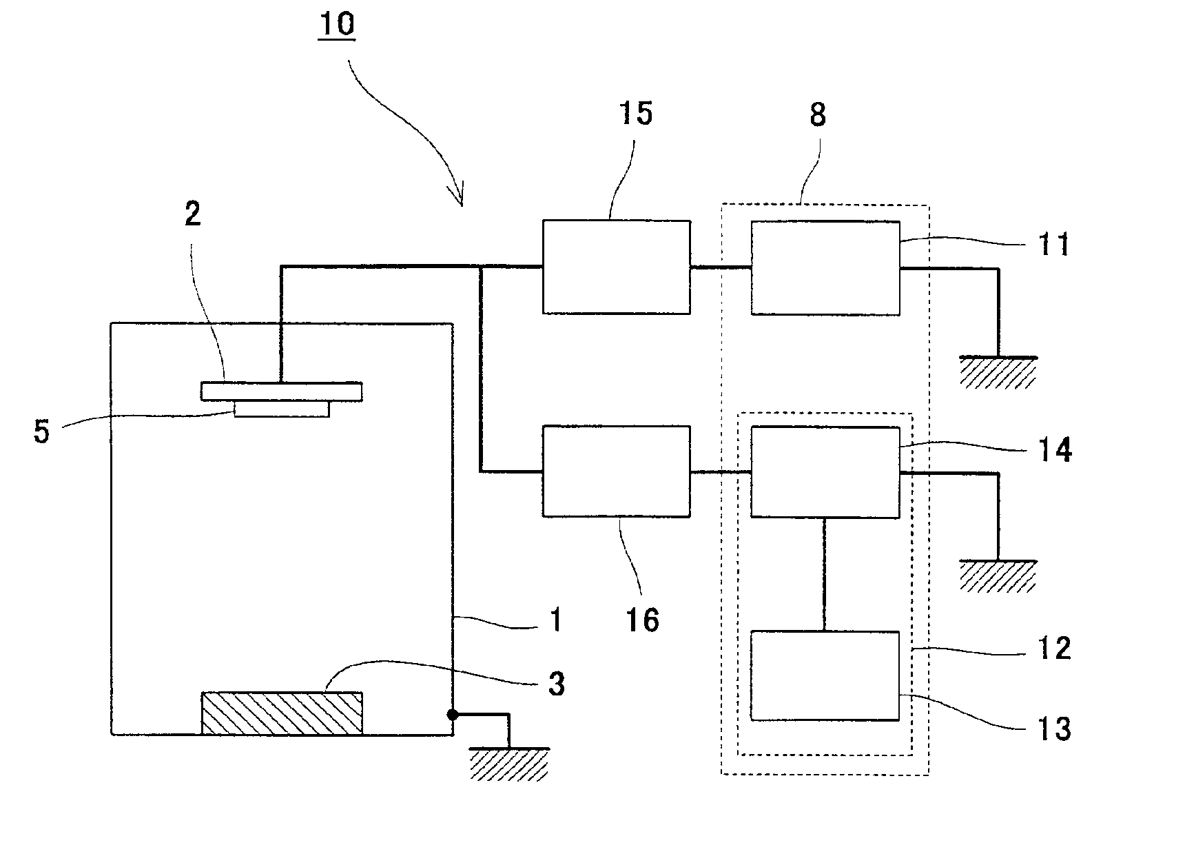
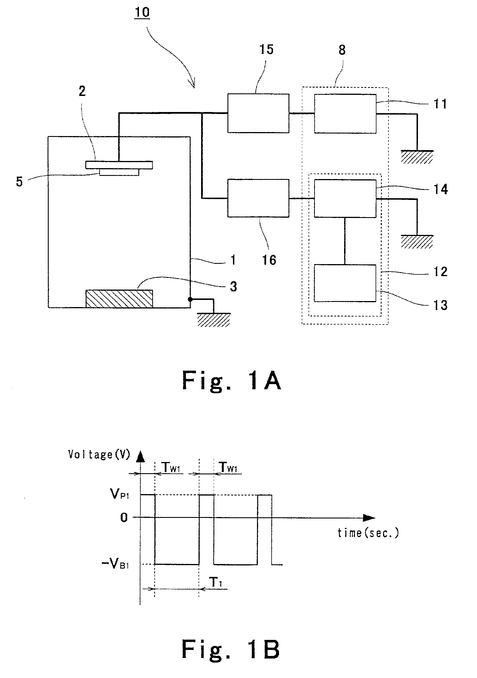
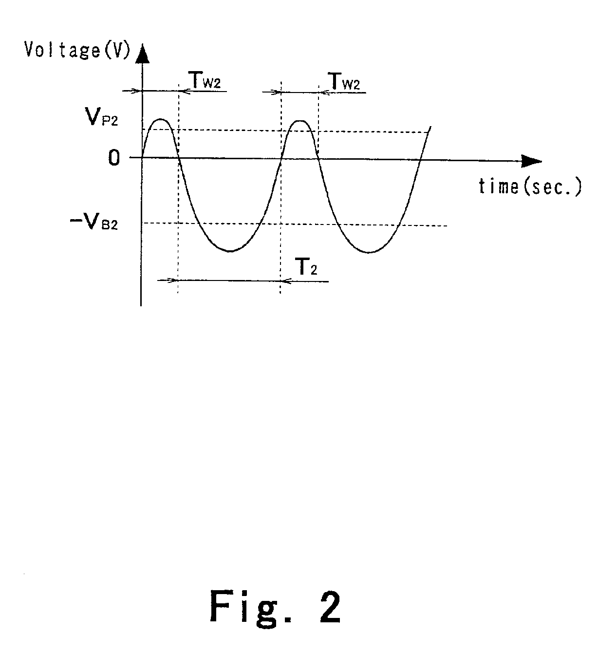
FIG. 1A is a schematic view showing a configuration of an ion plating device 10 according to an embodiment of the present invention. Referring now to FIG. 1A, the device 10 comprises a vacuum chamber 1 and a power supply unit 8. The power supply unit 8 comprises a radio frequency (RF) power supply unit 11 and a bias power supply unit 12.

A substrate holder 2 is placed in an upper portion of the vacuum chamber 1 for holding a substrate 5 on which a film is to be formed. The substrate holder 2 is made of a conductive material and electric power is supplied from the RF power supply unit 11 and the bias power supply unit 12 to the inside of the vacuum chamber 1 through the substrate holder 2. The substrate holder 2 is adapted to be rotatably driven by a motor (not shown). The film is formed while the substrate holder 2 is rotated.

A vaporizing source 3 is placed in a lower portion of ...


PUM

PropertyMeasurementUnit
voltageaaaaaaaaaa
voltageaaaaaaaaaa
bias voltageaaaaaaaaaa

Abstract

In ion plating in which a substrate is held on a substrate holder placed in an evacuated vacuum chamber and plasma is generated in the vacuum chamber to be formed into a film, a bias voltage composed of a negative bias component having a predetermined negative voltage value for a predetermined output time and a pulse bias component corresponding to a pulse output having a constant positive value for a predetermined time and output with a cycle set in the rage of 1 kHz-1 GHz is supplied to the inside of the vacuum chamber through the substrate holder by a power supply unit.

Description

BACKGROUND OF THE INVENTION1. Field of the InventionThe present invention relates to an ion plating device and an ion plating method.2. Description of the Related ArtFilm formation by Ion plating is performed by supplying a constant voltage to the inside of a vacuum chamber to generate a discharge plasma from a material of a film and by applying the plasma to a substrate placed in the vacuum chamber to deposit the film on the substrate.Such film formation by ion plating is employed in film formation on various types of substrates, such as coating of a reflection film on a mirror. FIG. 4 is a schematic view showing a structure of an example of a device for forming a film by the ion plating.Referring to FIG. 4, an ion plating device 60 comprises a vacuum chamber 61, a substrate holder 62 placed in the vacuum chamber 61 for holding the substrate 65, a vaporizing source 63 for holding a material of a film and vaporizing the material in the vacuum chamber 61, a radio frequency (RF) power...

Claims


Application Information

Patent Timeline
Patent Type & Authority Patents(United States)
IPC IPC(8): C23C14/32H01J37/32C23C14/48B01J19/08
CPCC23C14/32H01J37/32706H01J37/32422C23C14/48
Inventor KOIZUMI, YASUHIRONOSE, KOUICHITOKOMOTO, ISAO
Owner SHIN MEIWA IND CO LTD
Why Eureka
Try Eureka