Projection exposure apparatus

Inactive Publication Date: 2005-03-08
NIKON CORP
View PDF98 Cites 8 Cited by
  • Summary
  • Abstract
  • Description
  • Claims
  • Application Information

AI Technical Summary

Benefits of technology

An object of the present invention is to provide a projection exposure apparatus capable of obtaining high resol

Problems solved by technology

However, it is so far difficult for the projection exposure apparatus of the above described type to shorten the wavelength of the irradiation light source (for example, 200 nm or shorter) because a proper optical material to make a transmissive optical member is not present and so forth.
Furthermore, the number of apertures formed in the projection optical system has approached its theoretical limit at present and therefore it is difficult to further enlarge the apertures.
Even if the aperture can be further enlarged, the focal depth expressed by ±λ/2NA2 rapidly decreases with an increase in the number of apertures, causing a critical problem to take place in that the focal depth required in a practical use further decreases.
However, the phase shift reticle has a multiplicity of unsolved problems because of a fact that the cost cannot be reduced due to its complicated manufacturing process and inspection and modification methods have not been established even now.
However, the above mentioned inclination irradiation method and the deformed light source method have a problem in that it is difficult to realize a uniform illuminance distribution over the entire surface of the reticle because the number of effective lens elements (that is, the number of secondary light sources capable of passing through the spatial filter) decreases and therefore an effect of making the illuminance uniform on the reticle deteriorates.
What is worse, the light quantity loss is excessive large in the system which has a member, such as the spatial filter, for partially cutting the irradi

Method used


Image

  • Projection exposure apparatus
  • Projection exposure apparatus
  • Projection exposure apparatus

Examples


first embodiment

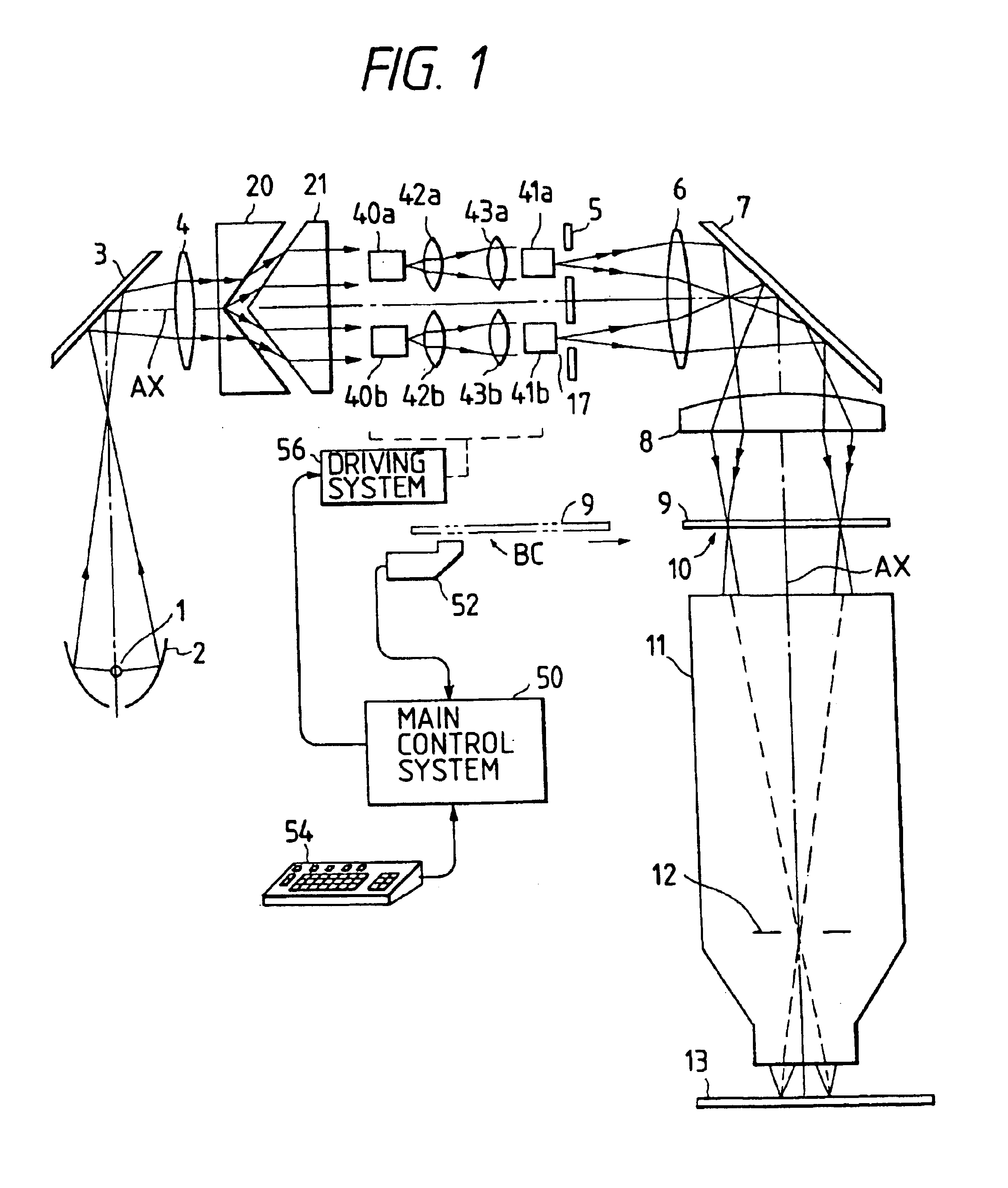
FIG. 1 illustrates the present invention in which two polyhedron prisms are used to form a light dividing optical system.

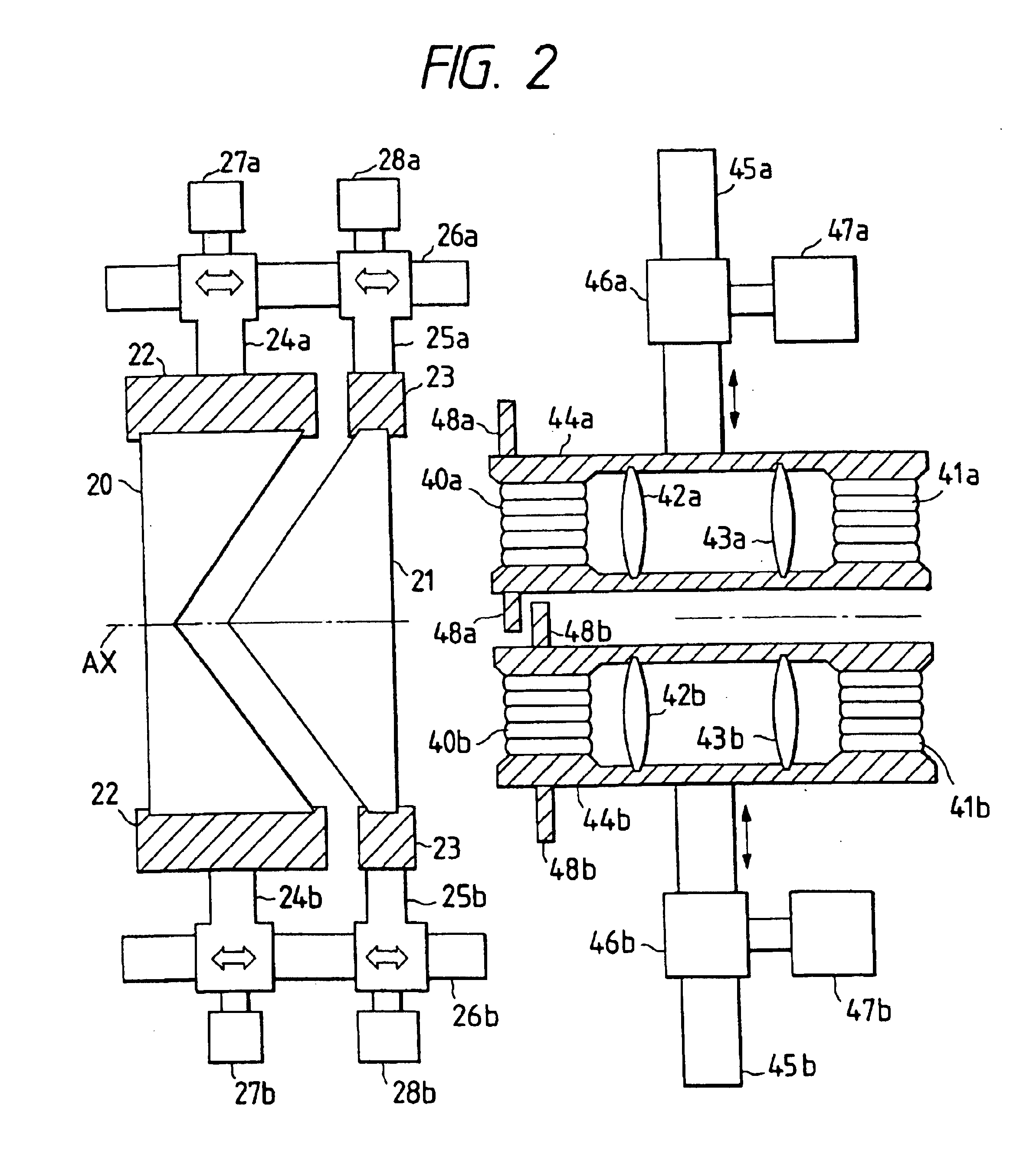
Irradiation light beams emitted from a light source 1 such as a mercury lamp are gathered by an elliptical mirror 2 before they are made to be substantially parallel beams by a bending mirror 3 and an input lens 4 so that the light beams are incident on light dividing optical systems 20 and 21. A light divider according to this embodiment comprises a first polyhedron prism 20 having a V-shape concave and a polyhedron prism 21 having a V-shape convex. The irradiation light beams are divided into two light beams by the refraction effect of the aforesaid two prisms 20 and 21. The divided light beams are respectively incident on second fly-eye lenses 40a and 40b.

Although two fly-eye lenses 40a and 40b are used in this embodiment, the quantity of them may be determined arbitrarily. Although the light dividing optical system is arranged to divide the light beams into t...


PUM


Abstract

A projection exposure apparatus including an irradiation optical system including a light source and irradiating a mask with irradiation light beams, a projection optical system for projecting an image of a pattern of the mask on a substrate, a plurality of first fly-eye type optical integrators each having an emission side focal plane disposed on a Fourier transformed surface with respect to the pattern of the mask in the irradiation optical system or on a plane adjacent to the same and having a center located at a plurality of positions which are eccentric from the optical axis of the irradiation optical system, a plurality of second fly-eye type optical integrators each having an emission side focal plane disposed on a Fourier transformed plane with respect to the incidental end of each of a plurality of the first fly-eye type optical integrators or on a plane adjacent to the same and being disposed to correspond to a plurality of the first fly-eye type optical integrators, and a light divider for dividing and causing the irradiation light beams from the light source to be incident on each of a plurality of the second fly-eye type optical integrators.

Description

BACKGROUND OF THE INVENTION1. Field of the InventionThe present invention relates to a projection exposure apparatus for use to form a pattern of a semiconductor integrated circuit, or a liquid crystal device, or the like.2. Related Background ArtWhen a circuit pattern of a semiconductor device or the like is formed, so-called photolithography technology is required. In this process, a method, in which a reticle (a mask) pattern is formed on a substrate such as semiconductor wafer, is usually employed. The surface of the substrate is applied with photosensitive photoresist so that a circuit pattern is transferred to the photoresist in accordance with an image irradiated with light, that is, in accordance with the shape of the pattern corresponding to a transparent portion of the reticle pattern. In a projection exposure apparatus (for example, a stepper), the image of a circuit pattern drawn on the reticle so as to be transferred is projected on the surface of the substrate (wafer) ...

Claims


Application Information

Patent Timeline
IPC IPC(8): G03F7/20
CPCG03F7/70075G03F7/70108G03F7/70891G03F7/70883G03F7/70858
Inventor SHIRAISHI, NAOMASAKUDO, YUJI
Owner NIKON CORP
Why Eureka
Try Eureka