
Method for manufacturing a surface acoustic wave device using a shear horizontal type surface acoustic wave

a surface acoustic wave and horizontal type technology, applied in the direction of piezoelectric/electrostrictive transducers, generators/motors, transducer types, etc., can solve the problems of complex and large ripples caused by transversal mode waves, input and output impedances exceeding 2 k, and cannot be used for actual products, so as to achieve the effect of reducing the complexity and eliminating the ripples

Inactive Publication Date: 2005-03-15
MURATA MFG CO LTD
View PDF18 Cites 9 Cited by
  • Summary
  • Abstract
  • Description
  • Claims
  • Application Information

AI Technical Summary

Benefits of technology

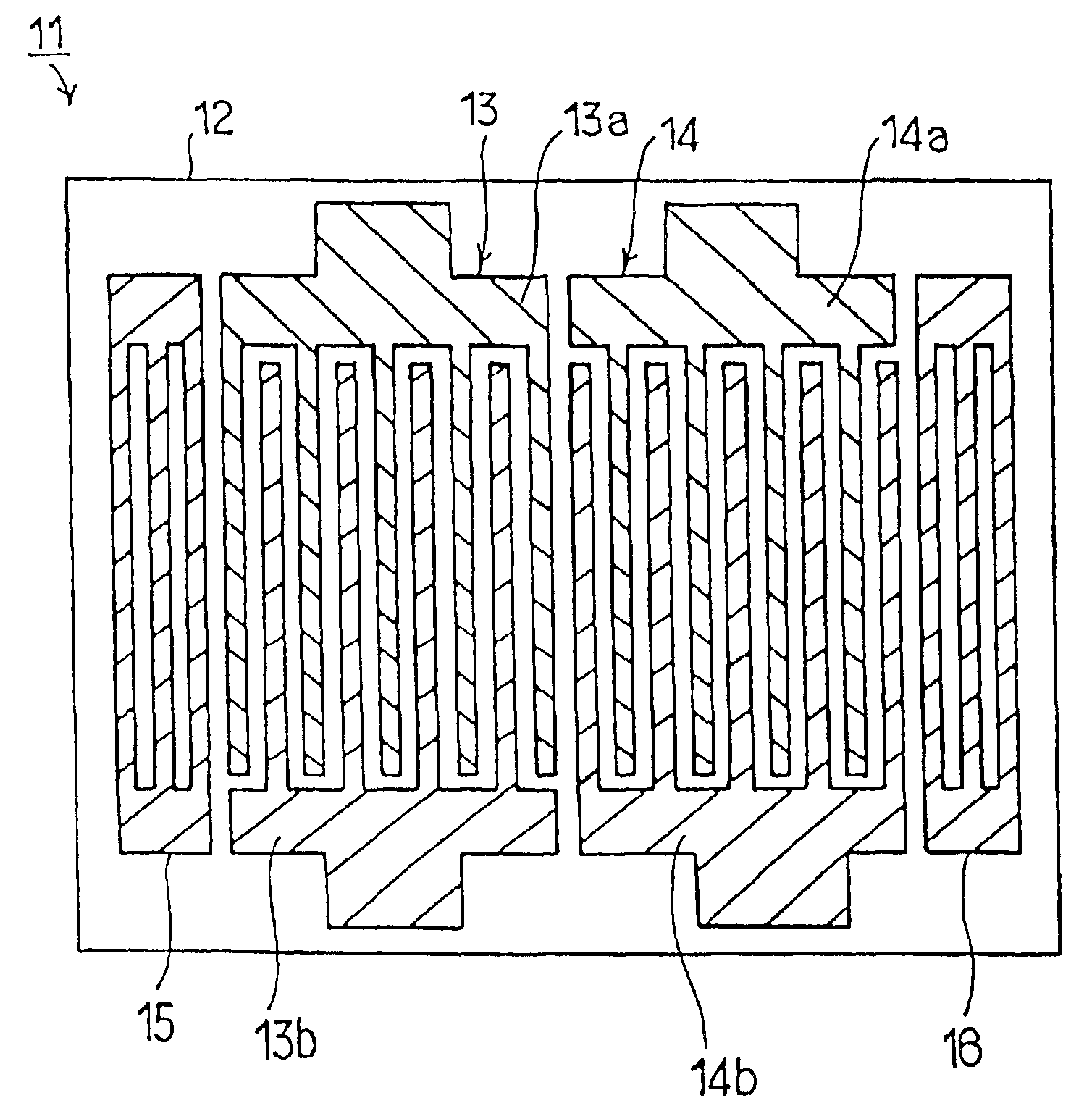
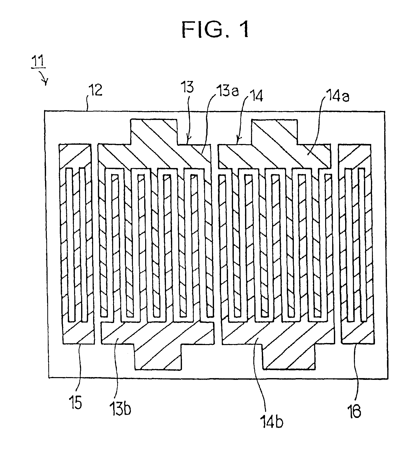
[0016]In order to overcome the problems described above, preferred embodiments of the present invention provide a surface acoustic wave device which has electrodes made from a material having a larger mass-load effect than aluminum, which is made to be very compact, which has a structure that minimizes and eliminates ripples caused by a transversal mode wave, and which uses an SH-type surface acoustic wave, and a manufacturing method therefor.
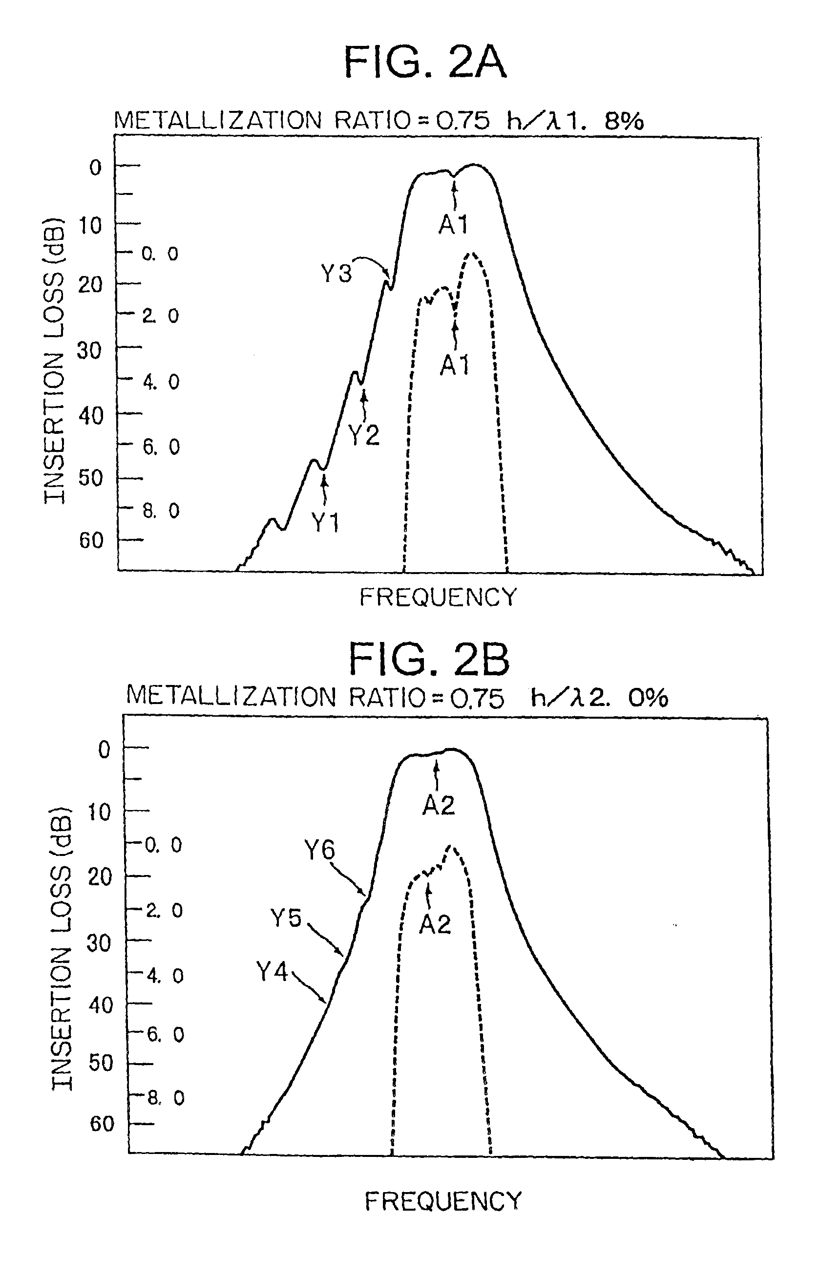
[0018]In the surface acoustic wave device, the metallization ratio “d” and the normalized film thickness h / λ of the interdigital transducer are preferably controlled so as to be within specific ranges such that the ripple caused by the transversal mode wave is about 0.5 dB or less. Therefore, even in a case in which an IDT made of electrodes having a larger mass-load effect than that of aluminum is used, and the number of the pairs of electrode fingers is reduced to make the device very compact, the ripple caused by the transversal mode wave is effectively suppressed and eliminated. Consequently, a compact surface acoustic wave device using an SH-type surface acoustic wave and having excellent frequency characteristics is provided.
[0022]In the surface acoustic wave device according to this preferred embodiment, since at least one interdigital transducer made from tantalum is disposed on the quartz substrate, and the normalized film thickness h / λ of the interdigital transducer falls in a range from about 0.6d+1.65 to about 0.6d+1.81, where “d” indicates the metallization ratio, ripples caused by a transversal mode wave are effectively suppressed. Therefore, even in a case in which at least one IDT made from tantalum is formed, and the number of the pairs of the electrode fingers in the IDT is reduced to make the device very compact, the ripple caused by the transversal mode wave is effectively suppressed and eliminated. Consequently, a compact surface acoustic wave device using an SH-type surface acoustic wave and having excellent frequency characteristics is provided.
[0024]In the surface acoustic wave device, since at least one interdigital transducer made from tungsten is disposed on the quartz substrate, and the normalized film thickness h / λ of the interdigital transducer is within a range from about 0.6d+0.85 to about 0.6d+1.30, ripples caused by a transversal mode wave are minimized and eliminated even in a case in which the number of the pairs of the electrode fingers in the IDT is reduced to make the device very compact. Consequently, a compact surface acoustic wave device using an SH-type surface acoustic wave and having excellent frequency characteristics is provided.
[0028]In the surface acoustic wave devices described above, the interdigital transducer may be disposed on the quartz substrate to constitute a one-port surface acoustic wave resonator. In this case, a compact one-port surface acoustic wave resonator having excellent frequency characteristics is provided.
[0031]In the above two cases, compact ladder-type and lattice-type filters having excellent frequency characteristics are provided.

Problems solved by technology

Consequently, when a longitudinally coupled resonator filter is produced, ripples caused by a transversal mode wave become complicated and very large, as indicated by arrows X in FIG.
When a quartz substrate and an IDT having 10 to 20 pairs of electrode fingers are used to provide a surface acoustic wave device, the input and output impedance exceeds 2 kΩ and is very high, so that the surface acoustic wave device cannot be used for actual products.
Therefore, the surface acoustic wave device cannot be made compact.
In the method B, weighting itself increases a loss of the surface acoustic wave device.
As a result, the surface acoustic wave device cannot be made compact.

Method used


Image

  • Method for manufacturing a surface acoustic wave device using a shear horizontal type surface acoustic wave
  • Method for manufacturing a surface acoustic wave device using a shear horizontal type surface acoustic wave
  • Method for manufacturing a surface acoustic wave device using a shear horizontal type surface acoustic wave

Examples


Embodiment Construction

en (W) is disposed on a quartz substrate.

[0046]FIG. 8 shows a range in which ripples caused by a transversal mode wave are eliminated according to preferred embodiments of the present invention, and shows the relationship between the metallization ratio and the normalized film thickness h / λ.

[0047]FIG. 9 is an outline plan view showing a modification of the surface acoustic wave device according to a preferred embodiment of the present invention.

[0048]FIG. 10 is a circuit diagram showing a ladder-type circuit defining a filter circuit including a surface acoustic wave device according to a preferred embodiment of the present invention.

[0049]FIG. 11 is an outline block diagram showing a transmitter and receiver in which a surface acoustic wave device according to a preferred embodiment of the present invention is used.

[0050]FIG. 12 is an outline block diagram showing another transmitter and receiver in which a surface acoustic wave device according to a preferred embodiment of the pre...


PUM

PropertyMeasurementUnit
impedanceaaaaaaaaaa
Euler anglesaaaaaaaaaa

Abstract

In a method of manufacturing a surface acoustic wave device using a Shear Horizontal type surface acoustic wave, at least one interdigital transducer (IDT) is made of a material having a larger mass-load effect than that of aluminum. The metallization ratio of the IDT and the normalization film thickness h / λ of the IDT are controlled such that ripple caused by a transversal mode wave is about 1.5 dB or less, where “h” indicates the film thickness of the electrodes and “h” indicates the wavelength of a surface acoustic wave.

Description

[0002]This application is a Div of Ser. No. 09 / 964,831 filed 9 / 27 / 01 U.S. Pat. No. 6,617,752BACKGROUND OF THE INVENTION[0003]1. Field of the Invention[0004]The present invention relates to surface acoustic wave devices, such as surface acoustic wave resonators and surface acoustic wave filters, and manufacturing methods therefor, and more particularly, to a surface acoustic wave device using a Shear Horizontal type (“SH-type”) surface acoustic wave and having a structure for reducing a transversal mode spurious ripple, and a manufacturing method therefor.[0005]2. Description of the Related Art[0006]In surface acoustic wave devices, aluminum or alloys including aluminum as a main component have conventionally been widely used as the electrode material of an interdigital transducer (IDT). At least one IDT is disposed on a piezoelectric substrate and reflectors or reflective end surfaces are disposed at both sides of the area where the IDT is located so as to define a resonator or a lo...

Claims


Application Information

Patent Timeline
Patent Type & Authority Patents(United States)
IPC IPC(8): H03H3/08H03H9/25H03H9/00H03H3/00H02N2/00H03H9/145H03H9/64
CPCH03H3/08H03H9/25H03H9/6436H03H9/6459H03H9/6483Y10T29/49128Y10T29/42Y10T29/49126Y10T29/49121H03H9/00
Inventor NAKAO, TAKESHIFUJIMOTO, KOJIKADOTA, MICHIOYONEDA, TOSHIMARO
Owner MURATA MFG CO LTD
Learn More