Hydrogen generator for uses in a vehicle fuel system

a fuel system and hydrogen generator technology, applied in the direction of machines/engines, manufacturing tools, instruments, etc., can solve the problems of affecting each system is complicated by one or more undesirable factors, so as to improve the efficiency of the engine, increase the electrode surface area, and simple electrode design

Inactive Publication Date: 2005-03-15
HYDROGEN TECH APPL
View PDF11 Cites 90 Cited by
  • Summary
  • Abstract
  • Description
  • Claims
  • Application Information

AI Technical Summary

Benefits of technology

The present invention overcomes the problems encountered in the prior art by providing in one embodiment an electrolyzer for electrolyzing water into a mixture comprising hydrogen gas and oxygen gas. The electrolyzer is adapted to deliver the gaseous mixture to the fuel system of an internal combustion engine that when combusted with the fuel, the efficiency of the engine is improved. The electrolyzer of the present invention comprises:an electrolysis chamber;an aqueous electrolyte solution comprising water and an electrolyte, the aqueous electrolyte solution partially filling the electrolysis chamber such that a gas reservoir region is formed above the aqueous electrolyte solution;two principal electrodes comprising an anode electrode and a cathode electrode, the two principal electrodes at least partially immersed in the aqueous electrolyte solution;one or more supplemental electrode at least partially immersed in the aqueous electrolyte solution and interposed between the two principle electrodes that are not connected to the two principal electrodes with a metallic conductor wherein the two principal electrodes and the one or more supplemental electrodes are held in a fixed spatial relationship;wherein a gas mixture comprising hydrogen gas and oxygen gas is generated by applying an electrical potential between the two principle electrodes. The utilization of interposed supplemental electrodes that are interposed between the anode and cathode allows for a greatly increased electrode surface area. Furthermore, the relatively simple design of the electrodes—as rectangular or square metallic shapes allows for the electrodes to be easily replaced. The gas mixture of hydrogen and oxygen formed in this embodiment is collected in the gas reservoir region which is adapted to deliver the mixture to the fuel system of an internal combustion engine.
In another embodiment of the present invention, a method for improving the fuel efficiency of an internal combustion engine is provided. The method comprises using the electrolyzer of the present invention in conjunction with an internal combustion engine. An electrical potential is applied to the two principal electrodes of the elecrolyzer thereby caused the electrolyzer to generate a mixture of hydrogen gas and oxygen gas. The gas mixture is then combined with the fuel in the fuel system of the internal combustion engine before the fuel is combusted in the internal combustion engine.

Problems solved by technology

However, hydrogen is a flammable gas that is potentially explosive.
Although each of these systems may increase fuel efficiency, each system is complicated by one or more undesirable features.
For example, the prior art systems do not have components that are readily removed and replaced by the end users.
Furthermore, these electrolysis systems tend to have electrodes that do not have a very high surface area.

Method used


Image

  • Hydrogen generator for uses in a vehicle fuel system
  • Hydrogen generator for uses in a vehicle fuel system
  • Hydrogen generator for uses in a vehicle fuel system

Examples


Embodiment Construction

)

Reference will now be made in detail to presently preferred compositions or embodiments and methods of the invention, which constitute the best modes of practicing the invention presently known to the inventors.

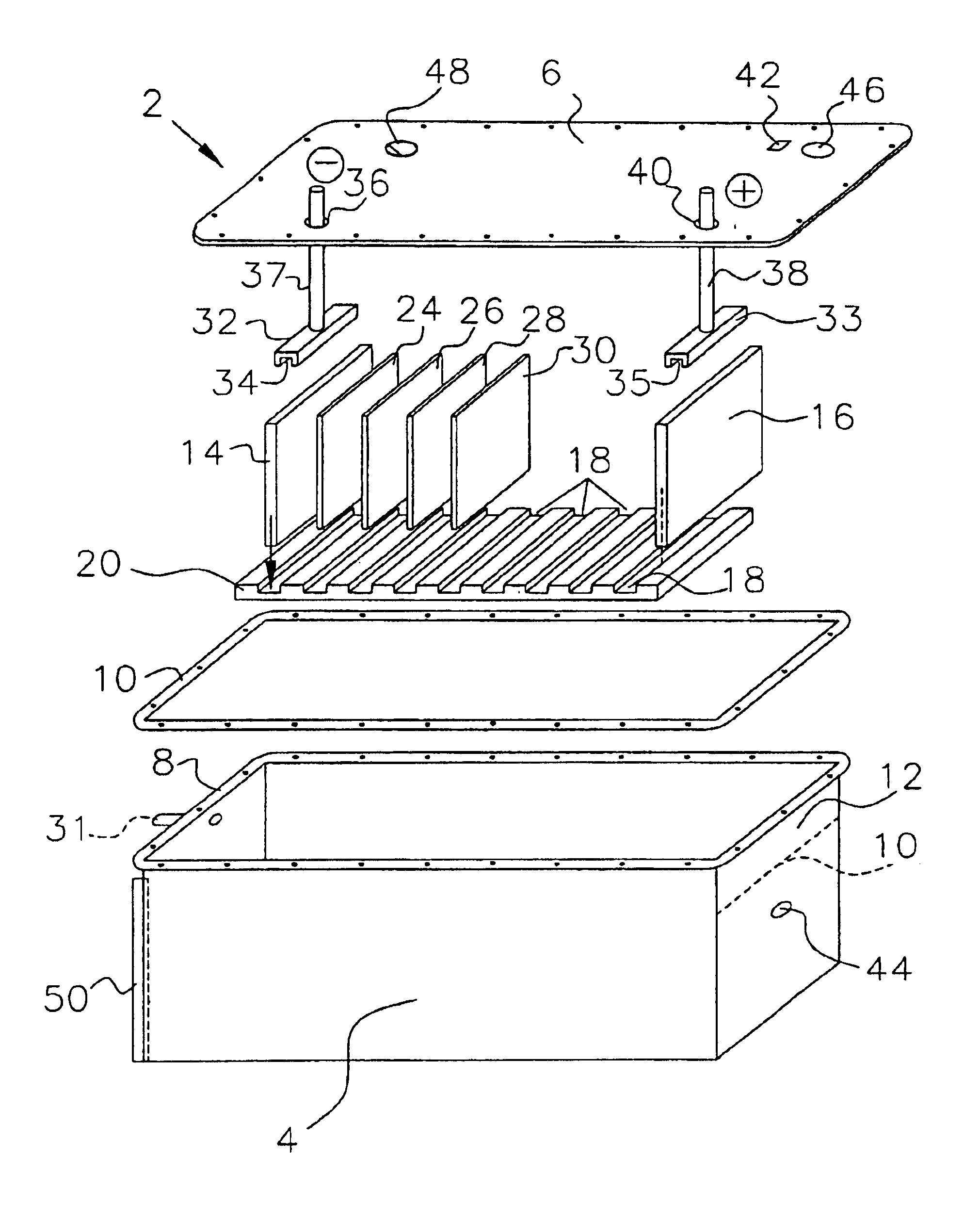
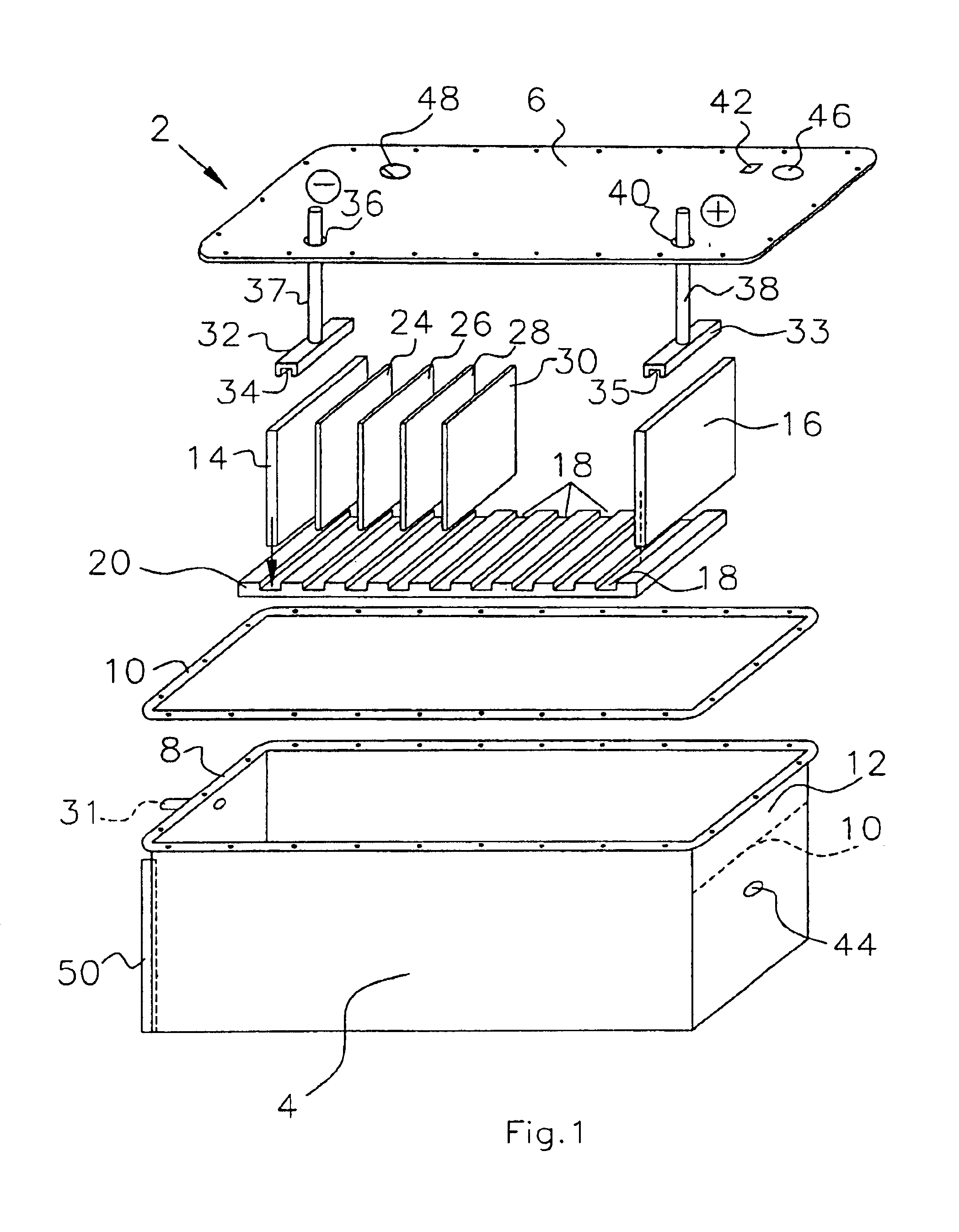
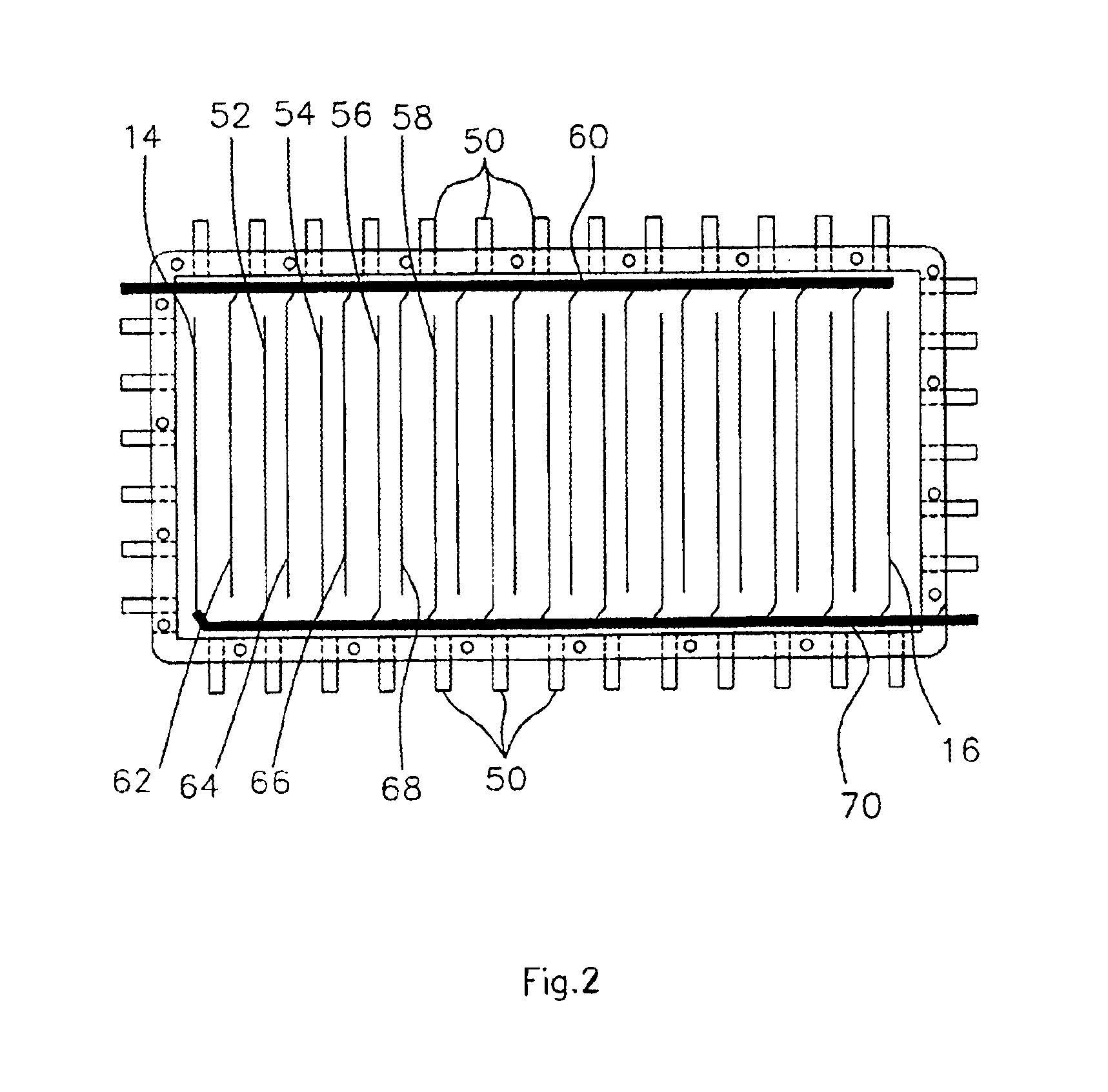
The term “electrolyzer” as used herein refers to an apparatus that produces chemical changes by passage of an electric current through an electrolyte. The electric current is typically passed through the electrolyte by applying a voltage between a cathode and anode immersed in the electrolyte. As used herein, electrolyzer is equivalent to electrolytic cell.

The term “cathode” as used herein refers to the negative terminal or electrode of an electrolytic cell or electrolyzer. Reduction typically occurs at the cathode.

The term “anode” as used herein refers to the positive terminal or electrode of an electrolytic cell or electrolyzer. Oxidation typically occurs at the cathode.

The term “electrolyte” as used herein refers to a substance that when dissolved in a suitable solvent or...


PUM

PropertyMeasurementUnit
distanceaaaaaaaaaa
distanceaaaaaaaaaa
distanceaaaaaaaaaa

Abstract

The present invention discloses an electrolyzer for electrolyzing water into a gaseous mixture comprising hydrogen gas and oxygen gas. The electrolyzer is adapted to deliver this gaseous mixture to the fuel system of an internal combustion engine. The electrolyzer of the present invention comprises one or more supplemental electrode at least partially immersed in an aqueous electrolyte solution interposed between two principle electrodes. The gaseous mixture is generated by applying an electrical potential between the two principal electrodes. The electrolyzer further includes a gas reservoir region for collecting the generated gaseous mixture. The present invention further discloses a method of utilizing the electrolyzer in conjunction with the fuel system of an internal combustion engine to improve the efficiency of said internal combustion engine.

Description

BACKGROUND OF THE INVENTION1. Field of the InventionThe present invention is related to an apparatus and method of improving the fuel efficiency of an internal combustion engine, and in particular, to an apparatus and method for hydrolyzing water into a mixture comprising hydrogen gas and oxygen gas to be combined with fuel used in an internal combustion engine.2. Background ArtFederal regulations force automobile manufacturers to constantly seek improvements in fuel efficiency and emissions control. Such governmental regulations have provided a significant impetus for the development of alternative fuel vehicles as well as improvements in vehicle catalytic conversion systems. Alternative fuel sources for automobile applications include natural gas, propane, wood alcohol, hydrogen fuel cells, and electricity. Although the future for each of these alternative sources is promising, considerable improvements are required for each before commercially viable products will be available.Th...

Claims


Application Information

Patent Timeline
Patent Type & Authority Patents(United States)
IPC IPC(8): C25B9/06C25B9/17
CPCC25B9/06Y10S123/12C25B9/17
Inventor KLEIN, DENNIS
Owner HYDROGEN TECH APPL
Why Eureka
Try Eureka