Low-mass and compact stage devices exhibiting six degrees of freedom of fine motion, and microlithography systems comprising same

a stage device and compact technology, applied in the field of microlithography, can solve the problems of large stage device overall, inpractical, and inability to meet the needs of small scale, and achieve the effect of low overall mass and low magnetic field fluctuations

Inactive Publication Date: 2005-03-15
NIKON CORP
View PDF5 Cites 13 Cited by
  • Summary
  • Abstract
  • Description
  • Claims
  • Application Information

AI Technical Summary

Benefits of technology

In view of the shortcomings of conventional stage devices as summarized above, the present invention provides, inter alia, stage devices that exhibit, relative to conventional stage devices, lower magnetic-field fluctuations while retaining compactness and low overall mass.

Problems solved by technology

If H-type and I-type stage devices as summarized above were to be used in certain conventional charged-particle-beam (CPB) microlithography apparatus as reticle stages and / or substrate (wafer) stages, certain problems would arise, as follows.
Unfortunately, despite the advantages (summarized in the preceding paragraph) of stage devices having such configurations, the stage devices exhibit magnetic-field fluctuations that degrade exposure accuracy.
Magnetically shielding the linear motors is a conceivable countermeasure for these field fluctuations, but such a countermeasure tends to be excessively complex.
However, in the center of the cross-shaped stage configuration, the H-type or I-type stage configuration nevertheless is present, resulting in a very large stage device overall, which is impractical.
However, this type of linear motor has a special configuration and is expensive.
However, in a vacuum, no pre-load is applied If it is desired to increase the rigidity of the stage, many air bearings must be used, resulting in excessive complexity of the stage device.
Although it is conceivable for pressurization to be provided by magnetic-attraction force instead of a vacuum, such an approach is not suitable for use in a CPB microlithography apparatus in which magnetic-field fluctuations should be maximally suppressed.

Method used


Image

  • Low-mass and compact stage devices exhibiting six degrees of freedom of fine motion, and microlithography systems comprising same
  • Low-mass and compact stage devices exhibiting six degrees of freedom of fine motion, and microlithography systems comprising same
  • Low-mass and compact stage devices exhibiting six degrees of freedom of fine motion, and microlithography systems comprising same

Examples


Embodiment Construction

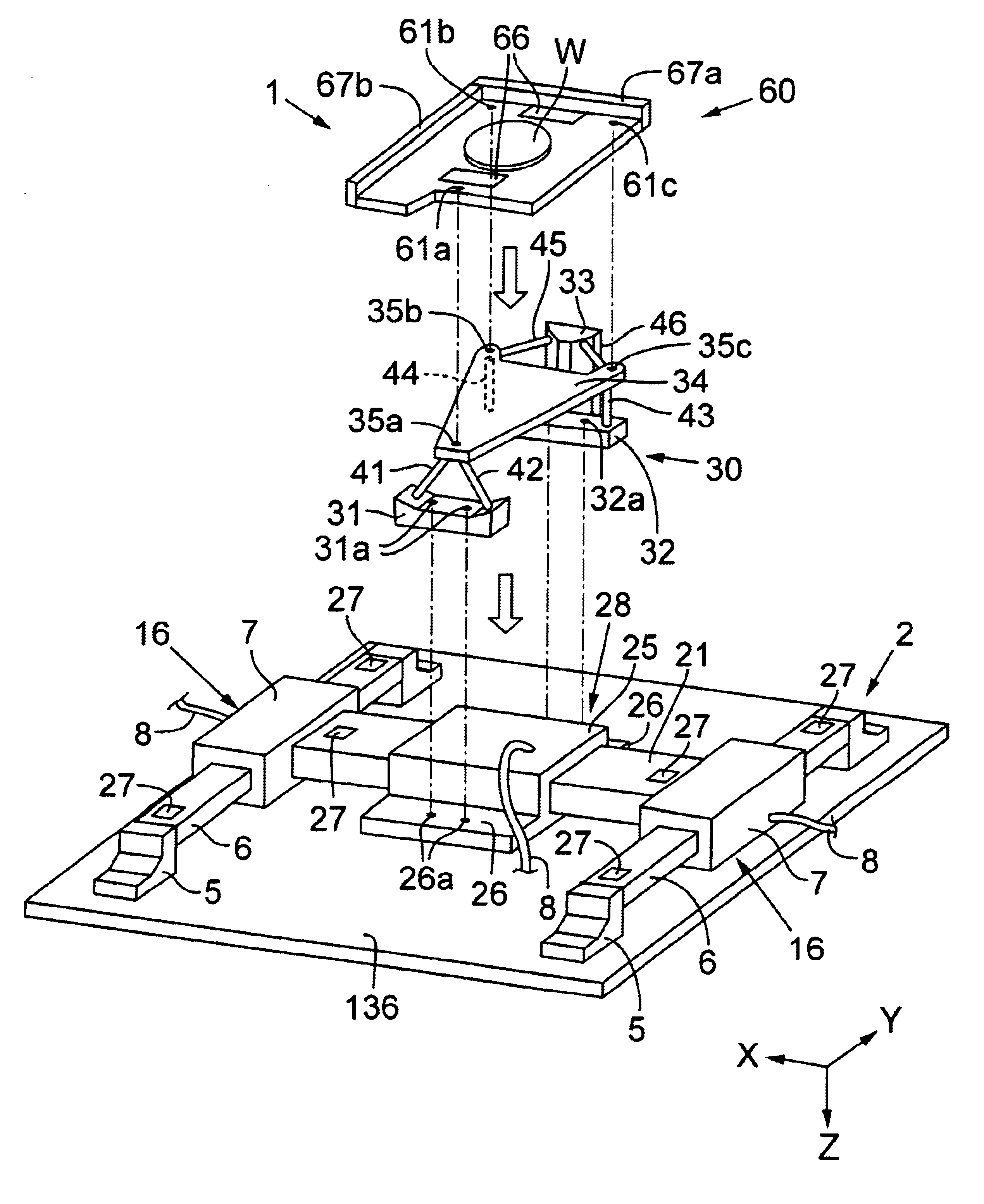
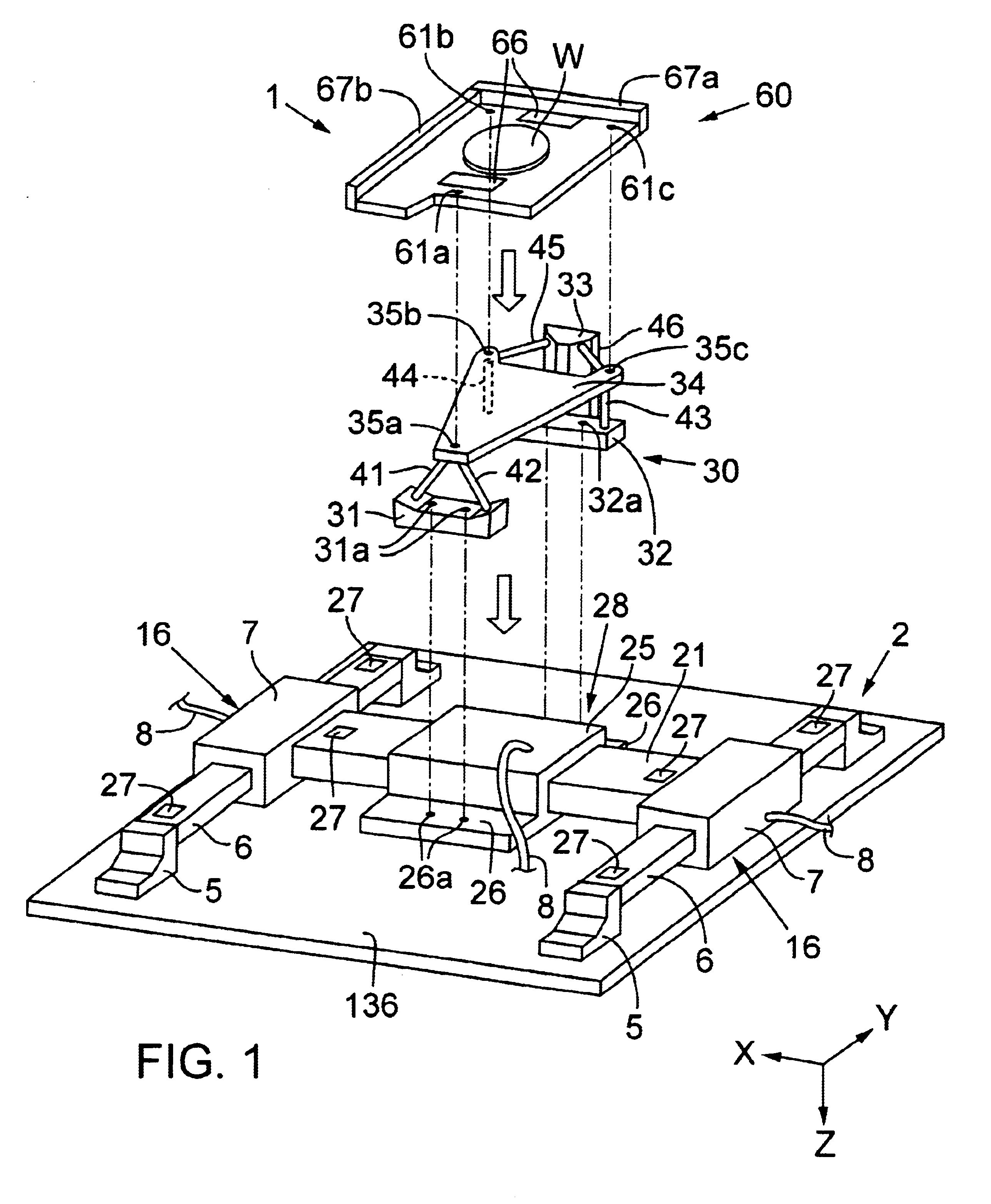
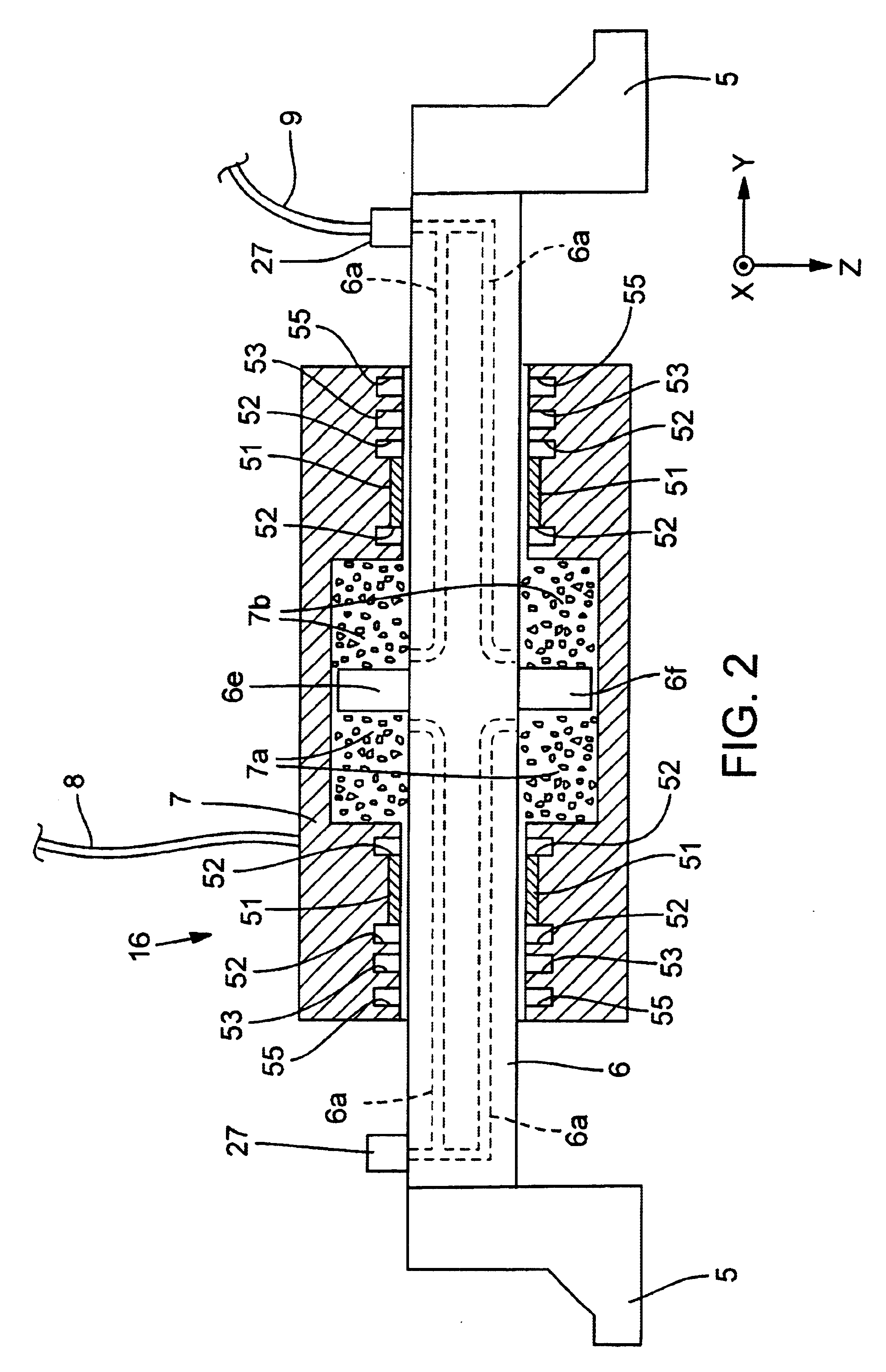
The invention is described below in the context of representative embodiments that are not intended to be limiting in any way. Also, the various embodiments are described in the context of an electron-beam microlithography system as a representative charged-particle-beam microlithography system. It will be understood that the principles described below are applicable with equal facility to microlithography systems utilizing an alternative type of charged particle beam, such as an ion beam, and to microlithography systems utilizing another type of energy beam, such as a VUV beam, X-ray beam, or EUV beam. The following also will be understood: (1) The stage devices described below can be used in general for positioning of an object in any of various environments, including a vacuum environment and / or in an environment in which suppression of fluctuating magnetic fields is important. (2) The reticle or mask (generally termed “reticle” herein) referred to herein can be a refractive or r...


PUM

PropertyMeasurementUnit
magnetic-fieldaaaaaaaaaa
magnetic fieldsaaaaaaaaaa
frictionaaaaaaaaaa

Abstract

Low-mass and compact stage devices are disclosed that exhibit, compared to conventional stage devices, reduced magnetic field fluctuations. An embodiment of such a stage device includes an X-Y coarse-movement stage portion that is drivable in the X-Y directions using respective air cylinders. A fine-movement stage portion is mounted on the X-Y coarse-movement stage portion. The fine-movement stage portion is drivable in any of the six degrees of freedom of motion (i.e., X, Y, Z, θX, θY, and θZ motions) relative to the coarse-movement stage portion. Such fine movements are achieved using six piezo actuators. In a stage device configured for use in a microlithography apparatus, a wafer table or reticle table can be mounted on the fine-movement table.

Description

FIELDThis disclosure pertains generally to microlithography (transfer-exposure of a pattern, defined on a reticle or mask (generally termed a “reticle” herein), to a “sensitive” substrate. Microlithography is a key technology used in the manufacture of microelectronic devices such as integrated circuits, displays, micromachines, and the like. More specifically, the disclosure pertains to stage devices as used in microlithography systems for accurate movement and positioning of the reticle and / or substrate (e.g., semiconductor wafer) during and in preparation for exposure. Even more specifically, the disclosure pertains to stage devices that are compact, lightweight, and produce no significant electric-field disturbance, and to microlithography systems comprising such stage devices.BACKGROUNDCurrently, so-called “H-type” and “I-type” X-Y stage devices represent the principal configurations of stage devices as used in optical microlithography systems. In each of these types of stage d...

Claims


Application Information

Patent Timeline
Patent Type & Authority Patents(United States)
IPC IPC(8): G03F7/20G12B5/00H01L21/027H01L21/68H02N2/00
CPCB82Y10/00B82Y40/00G03F7/70716H01J37/20H01J37/3174G03F7/70758H01J2237/202H01J2237/2005H01L21/027
Inventor TANAKA, KEIICHI
Owner NIKON CORP
Why Eureka
Try Eureka