Lens device for a camera with a stepping motor drive optimized for speed and power saving

a technology of stepping motor and lens device, which is applied in the field of lens device for a camera with a stepping motor drive optimized for speed and power saving, can solve the problems of inability to correct the magnitude of displacement of the front lens frame that is of a certain level or more, and may apply an unexpected extraneous force to the lens barrel holding the lens frame, so as to reduce the power consumption of the whole unit, the effect of moving faster and efficient driving and controlling

Inactive Publication Date: 2005-03-15
OLYMPUS CORP
View PDF15 Cites 1 Cited by
  • Summary
  • Abstract
  • Description
  • Claims
  • Application Information

AI Technical Summary

Benefits of technology

The first object of the present invention is to provide a lens unit capable of realizing efficient driving and controlling according to required conditions for driving, and contributing to reduction in power consumption of the whole unit. Specifically, when a storing action is executed for moving lens frames inward a camera body, driving and controlling is performed so that the lens frames can be moved more quickly. When a zooming action is executed as part of an imaging action, driving and controlling is performed so that the lens frames can be moved highly precisely.
Furthermore, according to the present invention, there is provided an electronic camera capable of producing and recording motion picture data and still picture data. Driving and controlling is performed in different driving modes between a zooming action to be executed as part of a motion picture imaging action and a zooming action to be executed as part of a still picture imaging action. It is therefore so that noise components including a noise sound emitted by a motor or the like during driving for zoom is prevented from being recorded during the execution of the motion picture imaging action. Besides, vibrations can be suppressed. This results in an electronic camera capable of recording excellent motion picture data and properly executing an imaging and recording action for producing still picture data.

Problems solved by technology

Moreover, an unexpected extraneous force may be applied to a lens barrel holding the lens frames.
Furthermore, for example, in an electronic camera or the like, an electric circuit or the like relevant to an imaging system that consumes a relatively large amount of power for execution of an imaging action must be operated.
However, when the stepping motor is used as a driving source for moving lens frames, the magnitude of displacement of the front lens frame that is of a certain level or more cannot be corrected unless the lens frames are returned to their reference positions (home positions).
This results in certain problems as described below.
In this case, if the displacement is very large, an error in camera control information becomes very large.
This may lead to impairment of image quality.
Because of these troubles, as long as a zoom lens barrel having a front lens frame capable of advancing or withdrawing freely is adapted to a conventional electronic camera or the like, it is difficult to design a barrel driving structure, which uses a stepping motor as a driving source, without an encoder.

Method used


Image

  • Lens device for a camera with a stepping motor drive optimized for speed and power saving
  • Lens device for a camera with a stepping motor drive optimized for speed and power saving
  • Lens device for a camera with a stepping motor drive optimized for speed and power saving

Examples


Embodiment Construction

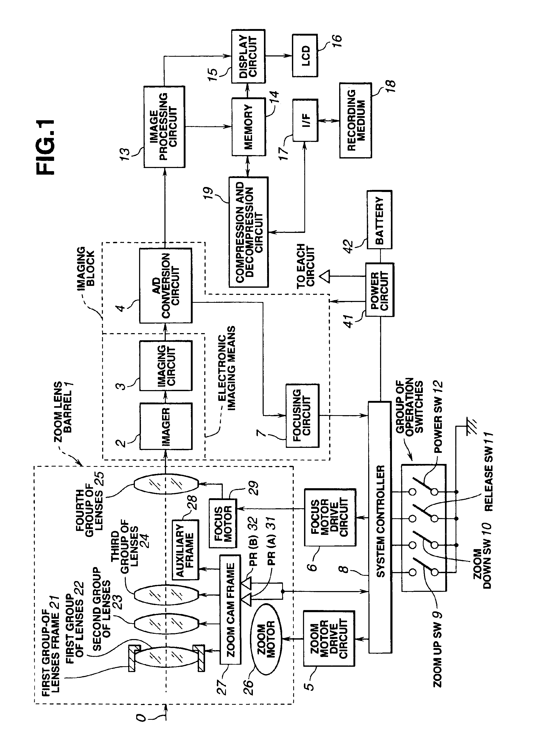
An embodiment of the present invention will be described below. Herein, an electronic camera (hereinafter called simply a camera) designed to electrically produce an image signal by utilizing an imaging device or the like is utilized for the following description.

All actions of a camera in accordance with an embodiment of the present invention are, as shown in the block diagram of FIG. 1, controlled by a system controller 8 serving as a control means. A release switch (SW) 11, a zoom up switch 9, a zoom down switch 10, and a power switch 12 which are included in a group of operation switches serving as an operating means are electrically connected to the system controller 8. The release switch 11 is used to generate a signal instructing start of imaging. The zoom up switch 9 is used to generate a signal instructing execution of a zooming up action. The zoom down switch 10 is used to generate a signal instructing execution of a zoom down action. The power switch 12 is used to generat...


PUM


Abstract

A lens unit consists of a plurality of lens frames, a stepping motor, and a driving control unit. The plurality of lens frames for holding an imaging optical system lies in a lens barrel and moves over a stowage interval and a zoom interval. The stowage interval is an interval between a position of stowage at which the lens frames are stowed and a ready-to-image position at which imaging is enabled. The zoom interval is an interval over which the ready-to-image position exists and a power varying action is executed. The stepping motor moves the plurality of lens frames. During execution of a thrusting action or storing action, the driving control unit drives and controls the stepping motor in a first driving mode. The thrusting action is executed for moving the plurality of lens frames from the position of stowage to the ready-to-image position. The stowing action is executed for moving the lens frames from any position within the zoom interval to the position of stowage. During execution of a zooming action for moving the lens frames over the zoom interval, the driving control unit drives and controls the stepping motor in a second driving mode in which a lower current is used than in the first driving mode.

Description

BACKGROUND OF THE INVENTION1. Field of the InventionThe present invention relates to a lens unit and an electronic camera using it. More particularly, this invention is concerned with a lens unit for driving a collapsible zoom lens using a stepping motor, and an electronic camera having the lens unit. In particular, this invention is concerned with driving and controlling of a lens barrel of the electronic camera.2. Description of the Related ArtIn recent years, cameras for achieving photography using photographic film or electronic cameras (hereinafter these types of cameras are generically called cameras) are demanded to have a compact camera body for convenience in portable use. The electronic cameras produce an electrical image signal using an imaging device or the like, and record the image signal on a recording medium or the like.Moreover, the cameras are requested to offer more advanced functions, or specifically, to include a high-precision automatic focusing (AF) unit, and ...

Claims


Application Information

Patent Timeline
Patent Type & Authority Patents(United States)
IPC IPC(8): G02B7/10H04N5/225
CPCG02B7/102H04N5/23296H04N5/23245H04N5/2254H04N23/55H04N23/673H04N23/667H04N23/69
Inventor FUJII, NAOKI
Owner OLYMPUS CORP
Why Eureka
Try Eureka