Light source device

a light source and light source technology, applied in the direction of optical radiation measurement, instruments, semiconductor lasers, etc., can solve the problems of low propagation property of light, information leakage to the external, high secrecy, etc., and achieve the effect of easy control of the distribution of light on the diffuser

Inactive Publication Date: 2005-03-15
JVC KENWOOD CORP A CORP OF JAPAN
View PDF10 Cites 34 Cited by
  • Summary
  • Abstract
  • Description
  • Claims
  • Application Information

AI Technical Summary

Benefits of technology

Specifically, a light source device of the present invention comprising one or more laser diodes which are laser light sources, one or more diffusers, a collimation optical system for collimating a light emitted from one or more diffusers. The collimator optical system is referred to as a collimator. The diffuser may be any one of a transmissive diffuser through which laser bundle transmits and are diffused, a reflective diffuser on which laser bundle is reflected and diffused, or a mixture diffuser which combines these diffusers. A reflective diffuser is simply a reflector whose diffuse reflection coefficient is higher than its mirror surface reflection coefficient. A laser bundle is emitted toward the diffuser. A light source device may have an optical focusing s...

Problems solved by technology

Moreover the possibility of an information leakage to the external due to rectilinear propagation property of the light is low and secrecy is high.
In this case the communication is usually unidirectional and very low-speed.
Among the disadvantages of this type of device, the most important are the need for a visual link without obstacles and the limitation of the level of exposure to which the human eye can be subjected, which restricts the power and collimation characteristics of the bundle.
This limitation has obliged the majority of these devices to use as radiation source an LED (Light Emitting Diode) or IRED (Infra Red Light Emitting Diode) instead of an LD (laser diode).
The use of LEDs or IREDs has restricted in practice not only the irradiance (power per unit of area) of the bundle transmitted, but also the transmission speed, since the switching time of these devices (in the order of a few nanoseconds) is comparatively long if they generate radiant power of around tens of milliwatts or more, which is generally necessary for wireless optical communications.
Its only disadvantage is that it is necessary to modify the characteristics of the bundle (for example, in general, it is necessary to reduce the irradiance of the bundle) if there exists the possibility of its reaching the eyes, which is the case in most applications of wireless communications and illumination.
However, this produces very high optical losses.
Nevertheless, if this expansion is carried out by means of a conventional optical system, that is, through a combination of lenses and mirrors, the laser system is not eye-safe.
This is due to the fact that viewing the b...

Method used


Image

  • Light source device
  • Light source device
  • Light source device

Examples


Embodiment Construction

Hereinafter, a light source device of embodiments of the present invention will be described with reference to the drawings.

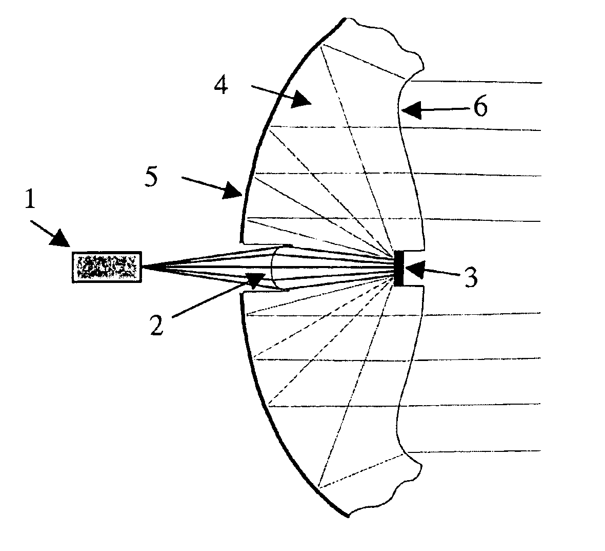
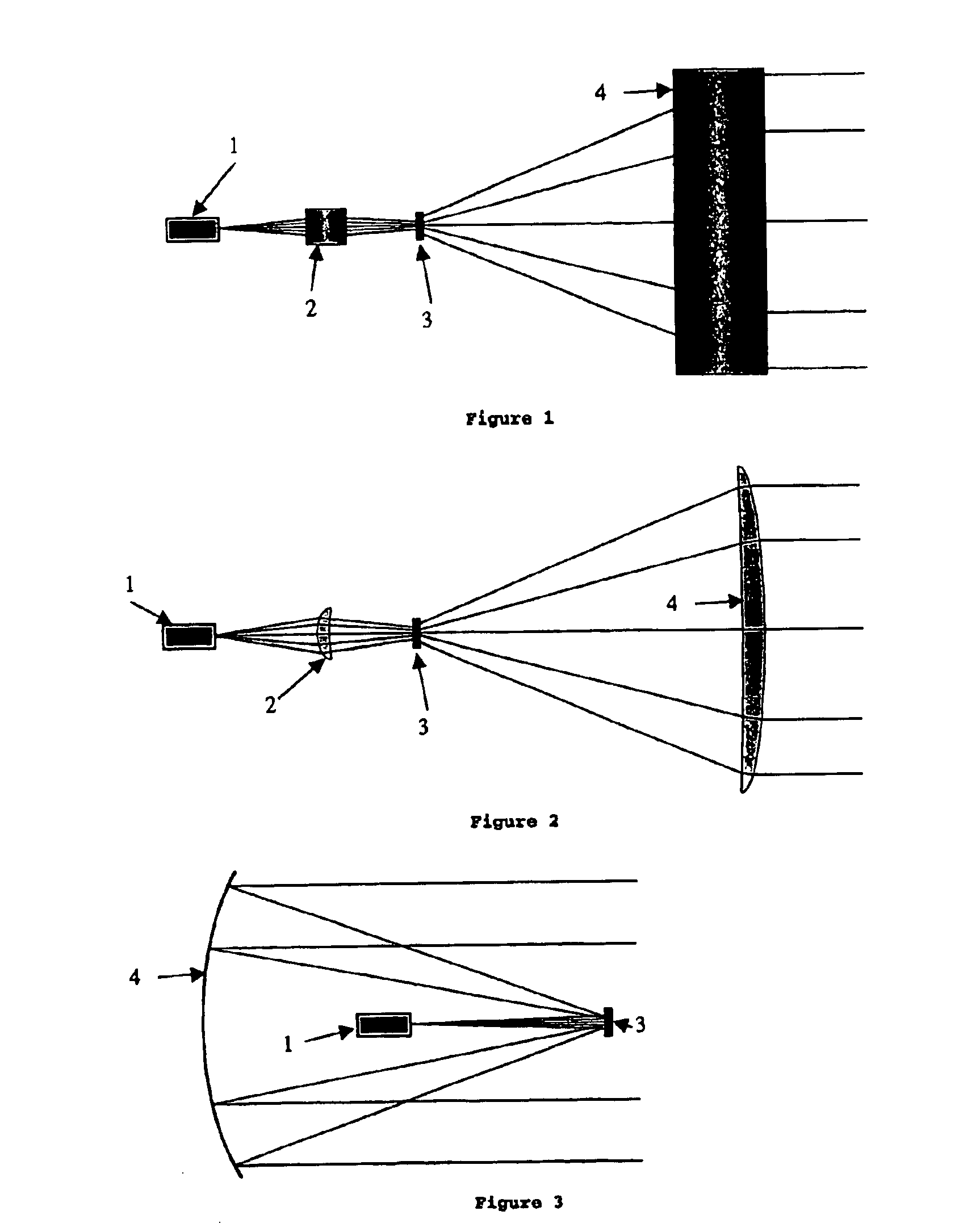
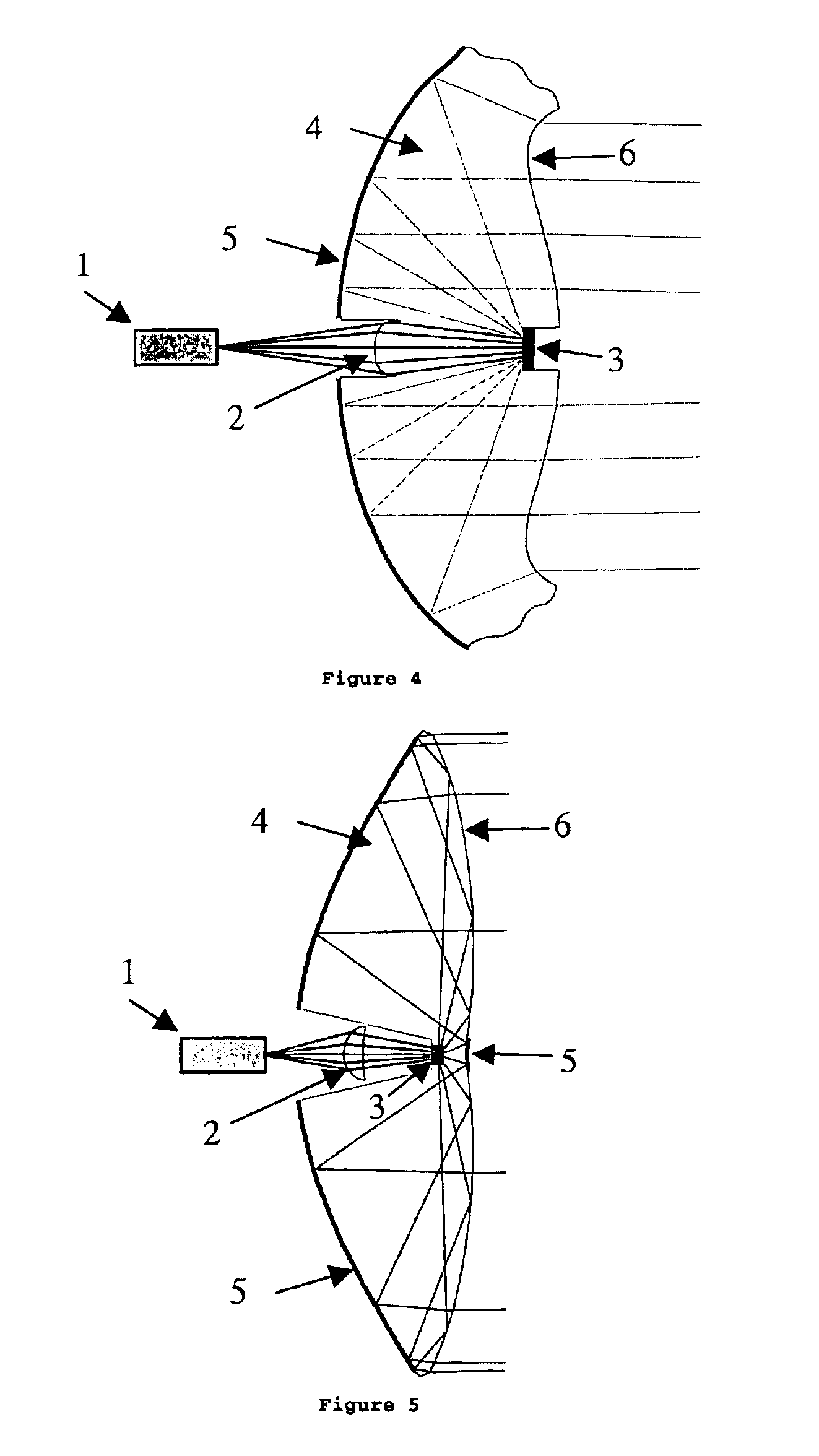
The present invention is a light source device comprising a laser light source for emitting monochromatic light or polychromatic light, a diffuser for diffusing the light bundle emitted from the laser light source and a collimated optical system referred to as a collimator which collimates the light bundle emitted from the diffuser, which is safe for human eyes and whose switching is performed at high speed. As a diffuser, a transmissive diffuser, a reflective diffuser, or a mixture diffuser which combines the transmissive diffuser and the reflective diffuser can be used, a laser light source directly emits the light bundle toward the diffuser, or injects the light bundle into the diffuser via the optical focusing system.

FIG. 1 is a schematic view showing a light source device applying the present invention.

The light source device comprising a laser light sourc...


PUM


Abstract

The present invention provides a light source device that is safe for human eyes and whose switching is performed at high speed. The light source device comprises one or more laser light sources (1) for emitting a monochromatic or polychromatic light beam, a diffuser (3), which may be transmissive, reflective, or a mixture thereof, for diffusing the light beam received directly from the laser light source or via an optical focusing system (2), and an optical collimator (4), which collimates the diffused light bundle emitted from the diffuser (3).

Description

BACKGROUND OF THE INVENTION1. Field of the InventionThe present invention relates to a light source device in which a laser diode is employed as a light source and used for a wireless optical communication.2. Description of the Related ArtIn recent years, there has been growing interest in wireless optical communications. There are several reasons for this as follows: the electromagnetic spectrum they use is not covered by current legislation, they are reliable systems, and they are not expensive. Moreover the possibility of an information leakage to the external due to rectilinear propagation property of the light is low and secrecy is high. The most widespread example of this type of communications can be found in the great majority of remote controls for electronic consumer goods. In this case the communication is usually unidirectional and very low-speed. Among the disadvantages of this type of device, the most important are the need for a visual link without obstacles and the l...

Claims


Application Information

Patent Timeline
IPC IPC(8): G02B5/02H01S3/00H01S5/00H01S5/068G02B3/00G02B17/08G02B19/00G02B27/09G02B27/18
CPCG02B5/0278G02B5/0284H01S3/005H01S5/06825H01S5/005
Inventor LOPEZ-HERNANDEZ, FRANCISCO-JOSEMINANO-DOMINGUEZ, JUAN-CARLOSBENITEZ-GIMENEZ, PABLOSAKAI, MASAHISAHIROHASHI, KAZUTOSHI
Owner JVC KENWOOD CORP A CORP OF JAPAN
Why Eureka
Try Eureka