Frequency-narrowed high power diode laser system with external cavity

a laser system and diode technology, applied in the field of diode lasers, can solve the problems of diode being destroyed and potential diode being destroyed, and achieve the effect of more usable output power and higher equivalent power

Inactive Publication Date: 2005-03-15
WISCONSIN ALUMNI RES FOUND
View PDF19 Cites 17 Cited by
  • Summary
  • Abstract
  • Description
  • Claims
  • Application Information

AI Technical Summary

Benefits of technology

In accordance with the present invention, a high power diode laser system utilizes an external cavity to narrow the spectral width of a high power diode laser having a multimode output to change the output power normally produced by the laser from a broad spectrum to a very narrow spectrum, so that more power is concentrated over a narrow spectral range which falls within the usable range for a particular application, such as optical pumping of noble gas samples for MRI. The total power output of the laser system is reduced a moderate amount from the output power provided from the laser alone, but concentrated within the narrow spectral range to provide a much higher equivalent power laser system. For example, a 4 watt output laser may have its output power narrowed in spectral width to provide 3 watts of output power in a usable narrow spectral range, providing more usable output power in the desired spectral range of interest than a much more expensive 15 watt laser.

Problems solved by technology

Excessive feedback would potentially destroy the diode (e.g., for some high power diodes, the diode would be destroyed if 30 percent or more of its power were to be fed back to it).

Method used


Image

  • Frequency-narrowed high power diode laser system with external cavity
  • Frequency-narrowed high power diode laser system with external cavity
  • Frequency-narrowed high power diode laser system with external cavity

Examples


Embodiment Construction

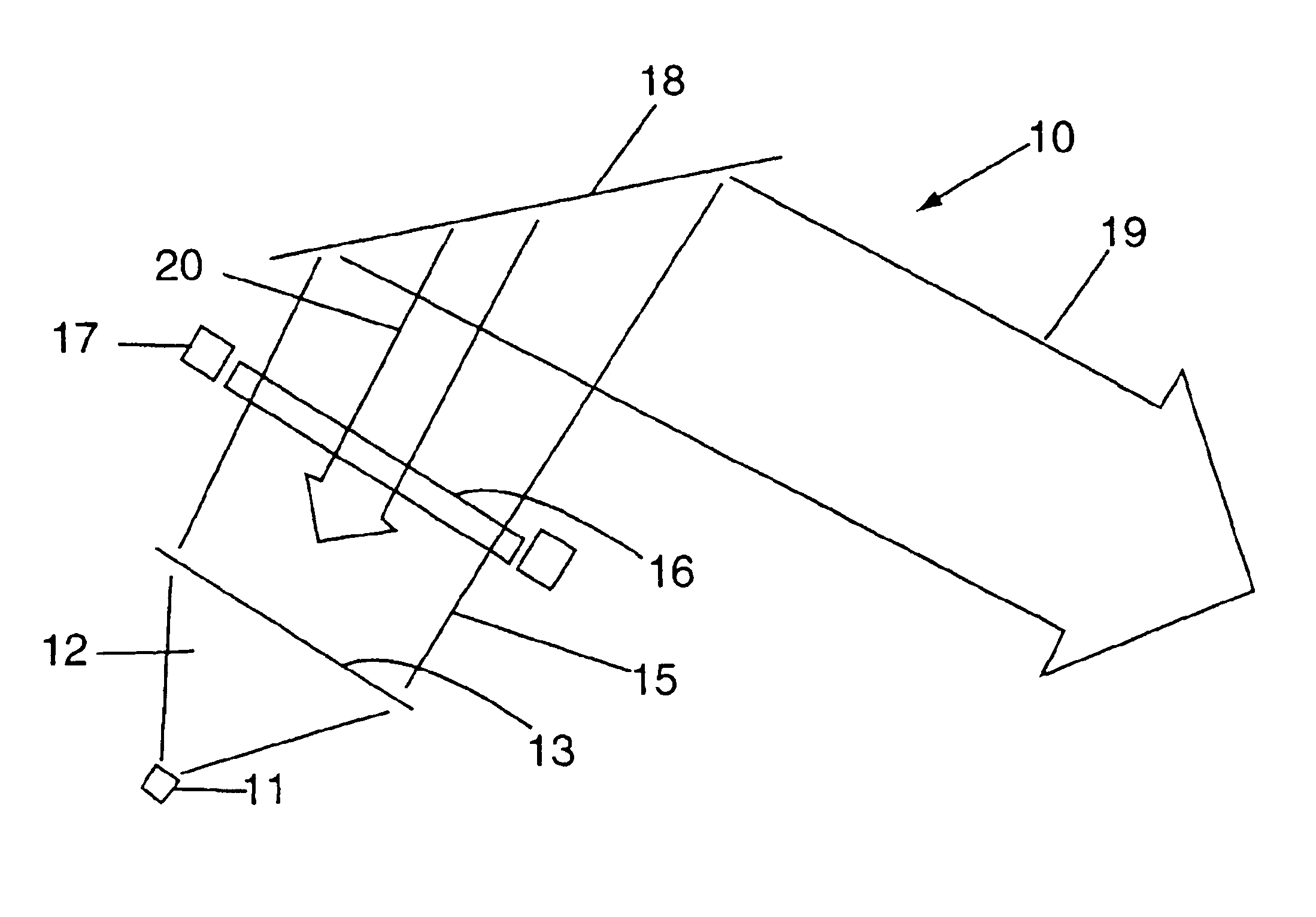
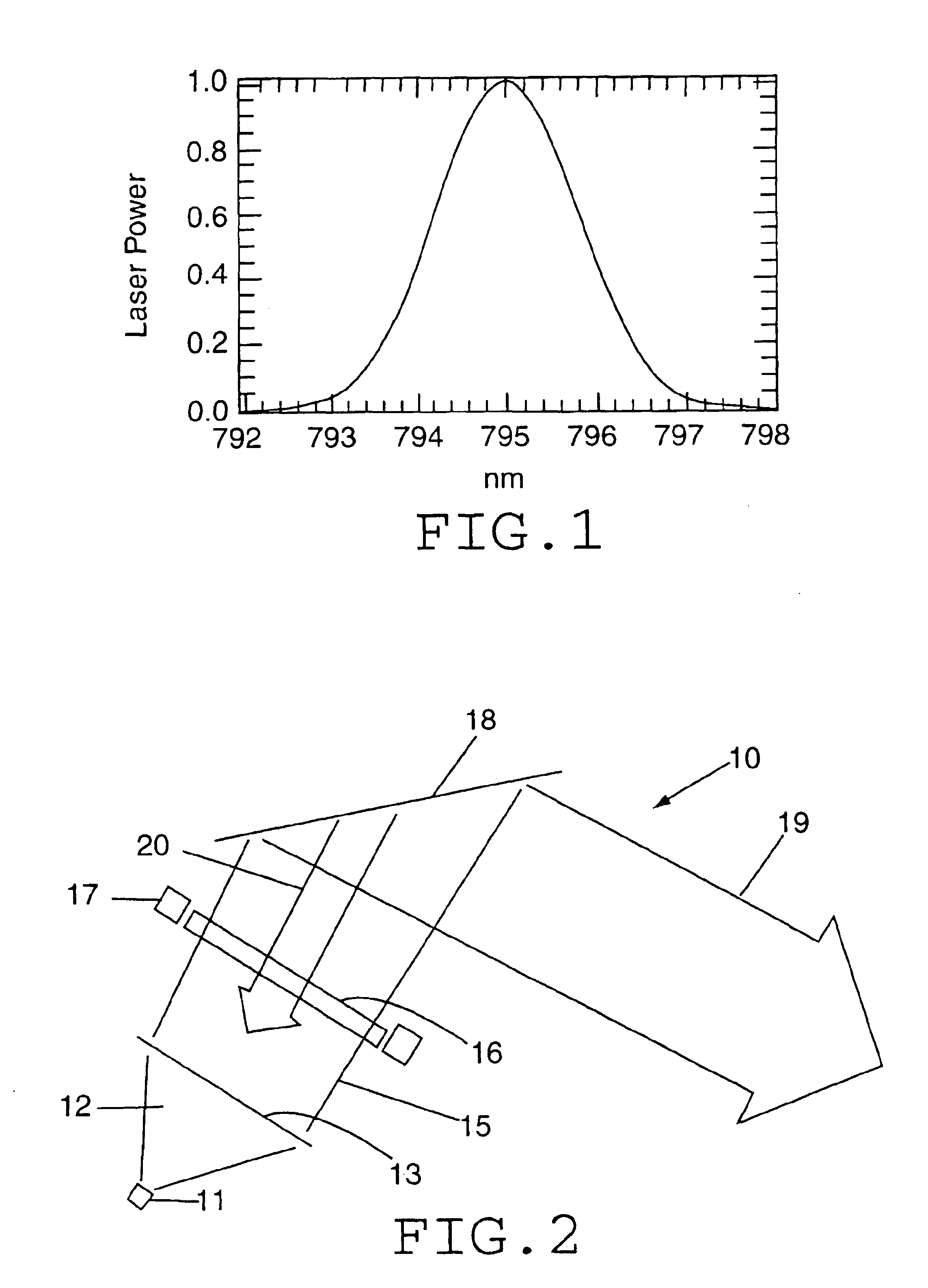
High power diode lasers, specifically, lasers with output powers greater than 1 watt, are much more expensive than low power diode lasers (generally, tens of milliwatts output power or less). For certain applications, however, the greater power output available from such high power lasers is essential. An example is in the production of laser-polarized noble gases for medical magnetic resonance imaging. However, the commercially available high power diode lasers provide their output power spread over a fairly wide spectral range, as illustrated in FIG. 1. In contrast to low power diode lasers, which have a single transverse mode, high power diode lasers have multiple transverse modes. Although the output laser spectrum of the high power laser may be centered at a particular wavelength (e.g., 795 nm as illustrated in FIG. 1), the output power may be spread over several nanometers, typically with a Gaussian distribution as shown in FIG. 1. For many applications, including the producti...


PUM


Abstract

A high power diode laser system utilizes an external cavity to narrow the spectral width of a high power multimode diode laser to change the output power normally produced by the diode from a broad spectrum to a very narrow spectrum. The power output of the laser system is concentrated over a narrow spectral range which falls within the useable range for particular applications, such as optical pumping of noble gas samples for magnetic resonance imaging. The output of the diode is received by a collimating element which directs the light on a beam path to a diffraction grating which is oriented at an angle to the incident beam. A portion of the beam may be directed from the diffraction grating to provide useable output light, and a portion of the light incident on the grating is directed back to be focused on the diode to provide feedback to cause the diode to preferentially lase at the wavelength of the light that is fed back. A polarization rotation element may be used to orient the polarization of the light passing through it to control the amount of feedback light.

Description

FIELD OF THE INVENTIONThis invention pertains generally to the field of diode lasers and particularly to high power diode laser systems.BACKGROUND OF THE INVENTIONHigh power diode laser arrays are now in use for a variety of technological applications. Commercially available diode array systems with high output power (greater than 1 watt) are currently relatively expensive. Although the cost of such systems is likely to decrease over time, a typical current cost for a 15 watt diode array is in the range of $25,000. Clearly, the users of such arrays wish to have as much usable laser light as possible. Unfortunately, much of the light that is emitted is not usable for many applications.One important use of high power diode lasers is for producing laser polarized noble gases for medical magnetic resonance imaging (MRI). As an example, a 15 watt laser array can be used to optically pump the noble gas sample. The user tunes the array to a wavelength at which the gas in the cell is activa...

Claims


Application Information

Patent Timeline
Patent Type & Authority Patents(United States)
IPC IPC(8): H01S3/10H01S5/00H01S5/14H01S5/40
CPCH01S5/141H01S5/005H01S5/0654H01S5/4062H01S5/143
Inventor WALKER, THAD G.CHANN, BIENNELSON, IAN A.
Owner WISCONSIN ALUMNI RES FOUND
Why Eureka
Try Eureka