Steam generator

a generator and steam technology, applied in the direction of steam generation using hot heat carriers, machines/engines, lighting and heating apparatus, etc., can solve the problems of reducing the effectiveness of the relevant heating area, unsatisfactory efficiency losses, and reducing steam generation, so as to achieve stable and reliable flow, low friction pressure loss, and high flow rate

Inactive Publication Date: 2005-03-22
SIEMENS AG
View PDF21 Cites 15 Cited by
  • Summary
  • Abstract
  • Description
  • Claims
  • Application Information

AI Technical Summary

Benefits of technology

It is certainly true that heated evaporator systems through which flow occurs downward normally lead to flow instabilities which are not tolerable precisely during use in once-through evaporators. However, during feeding with comparatively low mass-flow density, a natural-circulation characteristic of the steam generator tube can be achieved in a reliable manner due to the comparatively low friction pressure loss, which natural-circulation characteristic, when a steam generator tube is heated to a greater extent compared with a further steam generator tube, leads to a comparatively higher rate of flow of the flow medium in the steam generator tube heated to a greater extent. This natural-circulation characteristic, even when using the segments through which flow occurs downwards, ensures a sufficiently stable and reliable flow through the steam generator tubes.
In addition, such a characteristic can be achieved

Problems solved by technology

In particular in the case of steam generator tubes connected on the outlet side to a common collector, different heating of individual steam generator tubes may lead to a union of steam flows having steam parameters differing greatly from one another and thus to undesirable efficiency losses, in particular to comparatively reduced effectiveness of the relevant heating area and consequently reduced steam generation.
In addition, different heating of adjacent steam generator tubes, in particular in the region where they open into collectors, may result in damage to the steam generator tubes or the collector.

Method used


Image

  • Steam generator
  • Steam generator
  • Steam generator

Examples


Embodiment Construction

Reference will now be made in detail to the preferred embodiments of the present invention, examples of which are illustrated in the accompanying drawings, wherein like reference numerals refer to like elements throughout.

The same parts are provided with the same designations in all the figures.

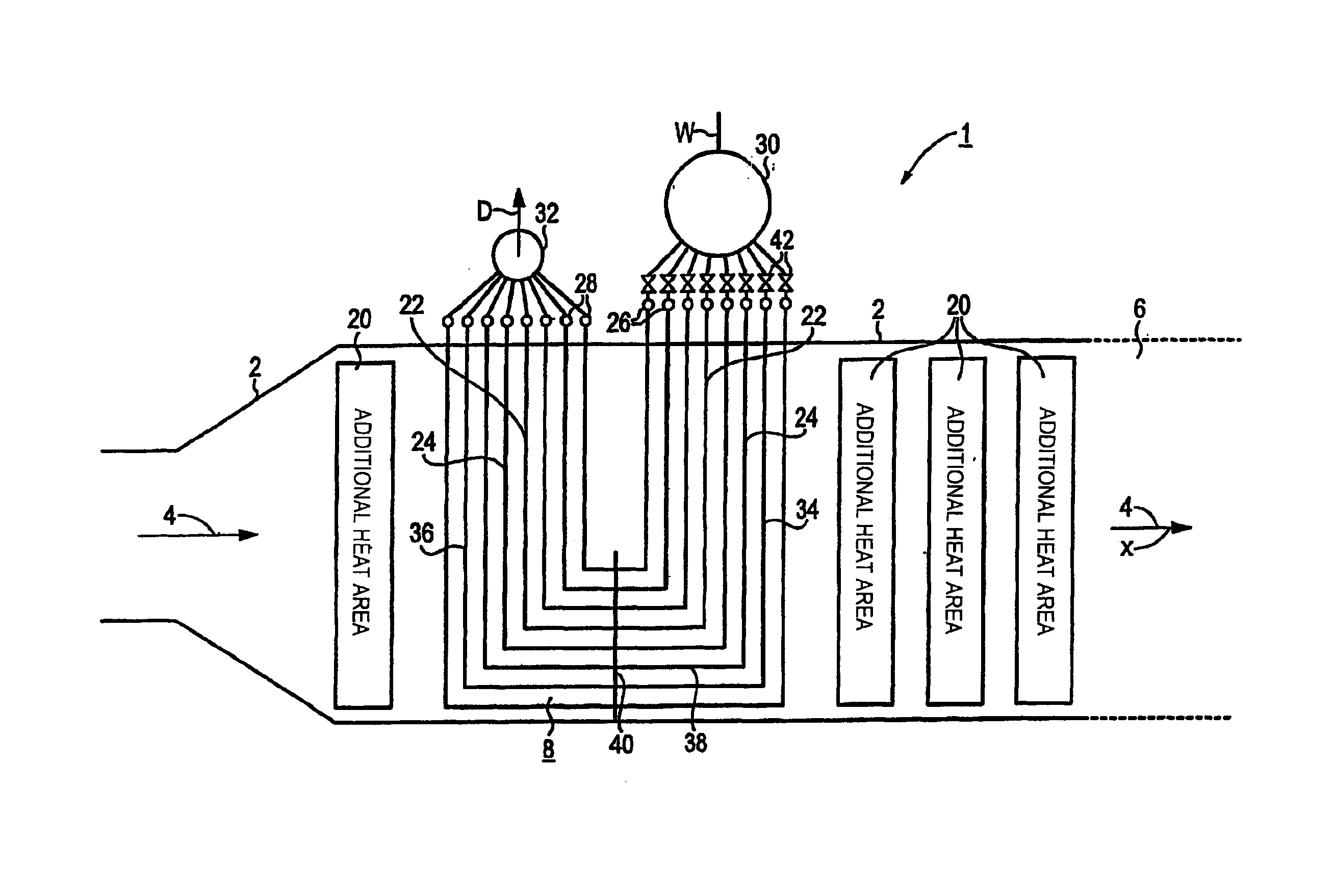
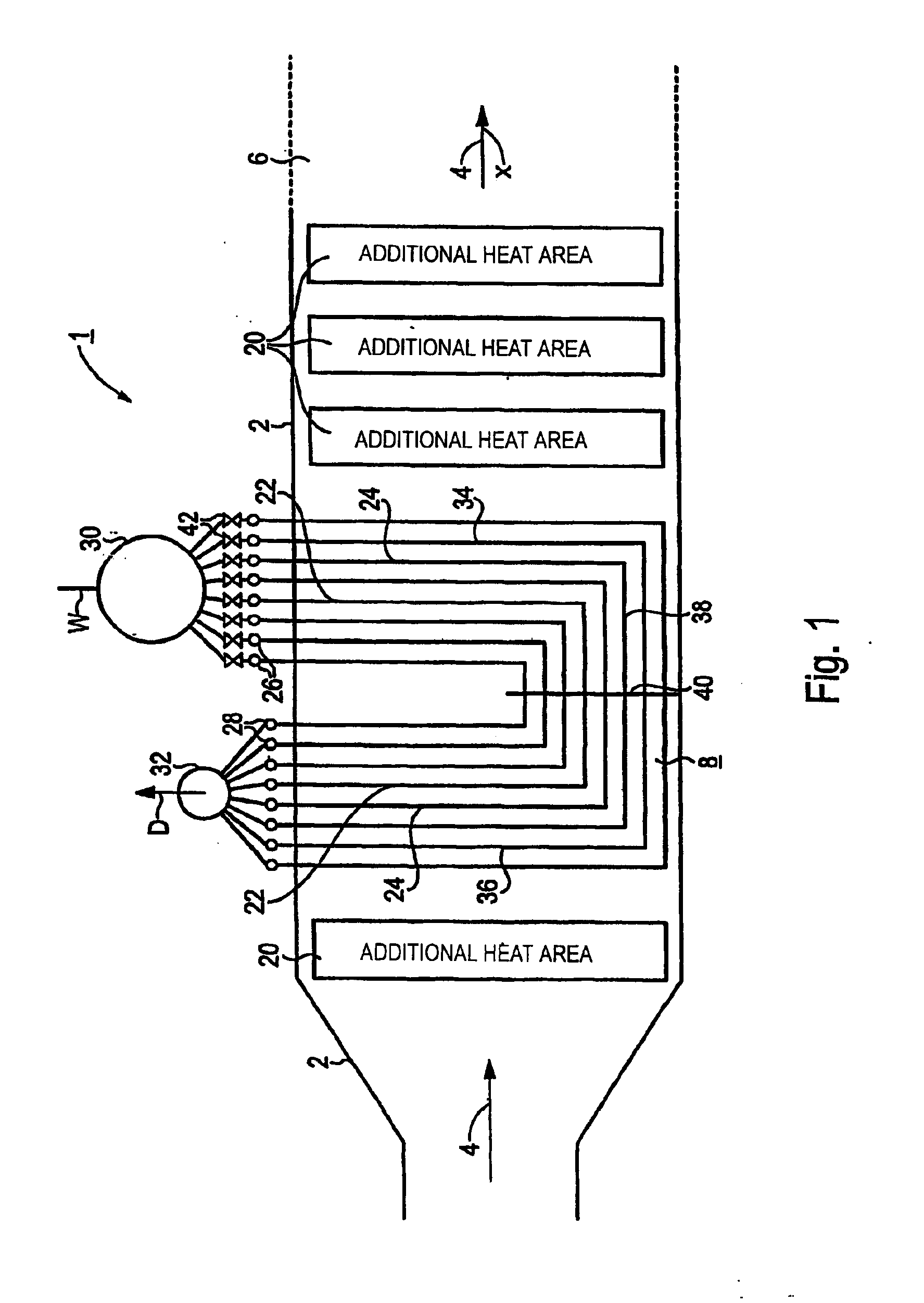
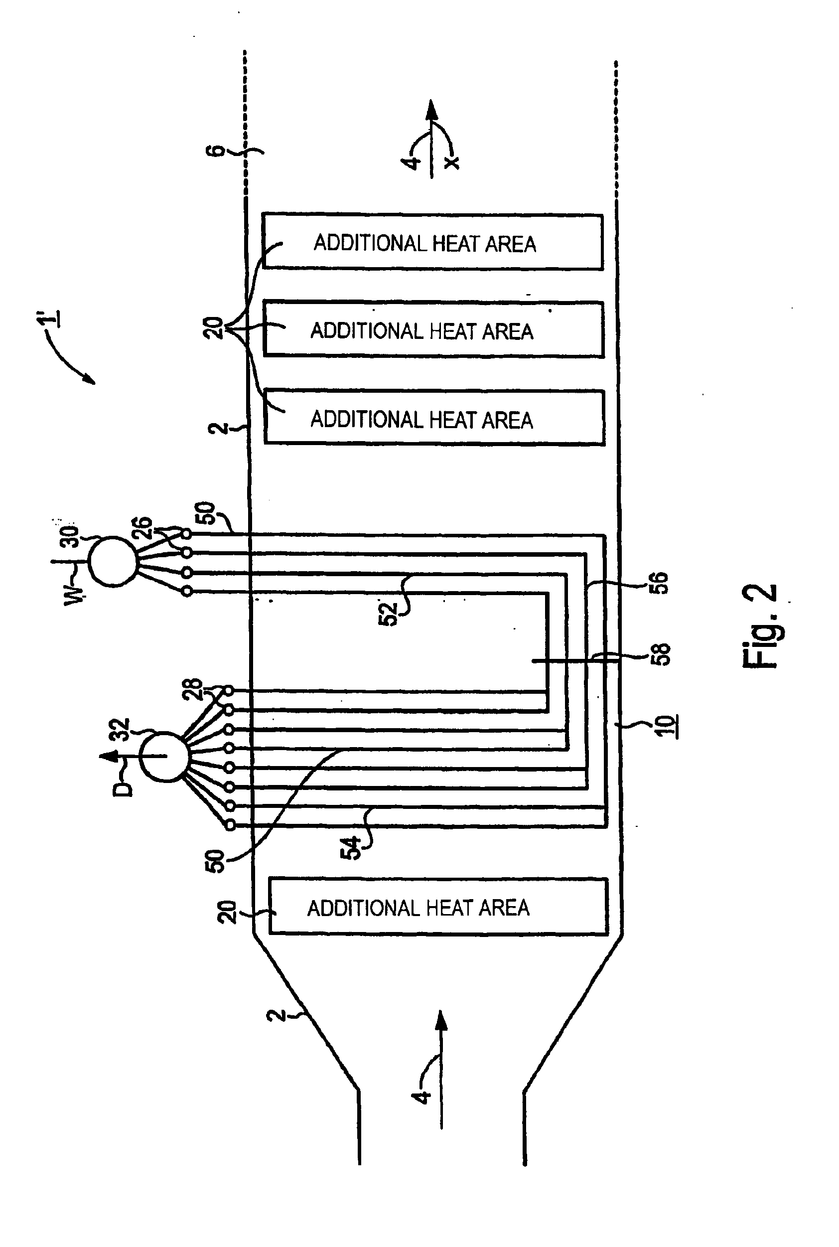
The steam generator 1, 1′, 1″ according to FIGS. 1, 2 and 3, respectively, is arranged like a heat-recovery steam generator on the exhaust-gas side downstream of a gas turbine (not shown in any more detail). The steam generator 1, 1′. 1″ has in each case an enclosing wall 2 which forms a heating-gas duct 6 for the exhaust gas from the gas turbine, through which heating-gas duct 6 flow can occur in an approximately horizontal heating-gas direction x indicated by arrows 4. A plurality of heating areas designed according to the once-through principle, and also referred to as once-through heating areas 8, 10 and 12, respectively, are arranged in each case in the heating-gas duct 6. In the exempla...


PUM


Abstract

A steam generator has a continuous heating surface located in a fuel gas channel that can be traversed in an approximately horizontal fuel gas directions. The continuous heating surface has a plurality of steam generator pipes that are connected in parallel for the passage of a flow medium and is designed in such a way that a steam generator pipe, which is heated to a greater extent than another steam generator pipe of the same continuous heating surface, has a higher throughput of the flow medium than the other steam generator pipe. The aim is to produce a low-cost steam generator with a particularly high level of mechanical stability, even when subjected to different thermal stresses. To achieve this, the or each steam generator pipe has a respective downpipe section, which is approximately vertical and through which the flow medium can flow downwards and a respective riser pipe section connected downstream of the downpipe on the flow medium side, which is approximately vertical and through which the flow medium can flow upwards.

Description

CROSS REFERENCE TO RELATED APPLICATIONSThis application is based on and hereby claims priority to German Application No. 10127830.6 filed on Jun. 8, 2001, the contents of which are hereby incorporated by reference.BACKGROUND OF THE INVENTIONThe invention relates to a steam generator in which a once-through heating area is arranged in a heating-gas duct through which flow can occur in an approximately horizontal heating-gas direction, which once-through heating area comprises a plurality of steam generator tubes connected in parallel to the throughflow of a flow medium and which is designed in such a way that a steam generator tube heated to a greater extent compared with a further steam generator tube of the same once-through heating area has a higher rate of flow of the flow medium compared with the further steam generator tube.In a gas- and steam-turbine plant, the heat contained in the expanded working medium or heating gas from the gas turbine is used for generating steam for th...

Claims


Application Information

Patent Timeline
IPC IPC(8): F02C6/18F22B1/18F22B1/00F22B37/00F22B37/14F01K23/10F22B37/10
CPCF02C6/18F22B37/143F22B1/1815F22B1/18
Inventor FRANKE, JOACHIMKRAL, RUDOLF
Owner SIEMENS AG
Why Eureka
Try Eureka