Enhanced remote plasma cleaning

Inactive Publication Date: 2005-03-22
APPLIED MATERIALS INC
View PDF38 Cites 7 Cited by
  • Summary
  • Abstract
  • Description
  • Claims
  • Application Information

AI Technical Summary

Benefits of technology

Some embodiments include a controller for controlling the cleaning system. The controller is coupled to a memory which includes a computer-readable program for directing control of the system. Some embodiments

Problems solved by technology

At any of the processing steps, the manufactured device may be exposed to a seemingly small amount of contamination which may result in a defect to the device.
For example, a contaminant particle as small as 100 Å in diameter can result in a fatal defect in a manufactured device.
The problem of contamination is exacerbated by the continual reduction in feature size and also by increasing wafer and die sizes.
More specifically, decreasing feature size results in potential defects from ever smaller contaminants.
Further, increasing wafer and die sizes subjects a high cost, larger die device to failure due to a single contaminant particle.
Alternatively, a large number of smaller die devices on a larger wafer are subject to contamination by a single contaminant particle.
Over time, contaminants form on the processing equipment in the form of both particulates and films.
It is possible for the contaminants to migrate to the device resulting in short circuits, open circuits, or other manufacturing defects.
In turn, these defects reduce manufacturing yields which increase processing costs and reduce profits.
The effectiveness and frequency of cleaning directly impacts processing costs and device yields.
While manually wiping the chamber is effective, it is time consuming and interferes with normal substrate processing.
First, as the fluorine radicals are formed in plasma outside the processing equipment and subsequently introduced into the equipment, they are subject to recombination before they react with contaminants in the processing equipment. More specifically, reactive F radicals recombine to form less reactive F2. These less reactive F2 molecules are not capable of cleaning the processing equipment. In a typical example, more than 90% of F radicals recombine without reacting in the cleaning process. This significant recombination loss occurs during transport from the remote plasma source to the equipment to be cleaned and results in low cleaning efficiency and increased cleaning costs.
The slower clean rate reduces cleaning efficiency and increases process costs.
Further, it is difficult to pinpoint the time at which the cleaning has been completed, i.e., when the last contaminant on the equipment has reacted with a cleaning radical so that it can be discharged from the equipment.
The difficulty in detection is due to the reliance of typical detection systems on testing of plasma within the equipment.
This difficulty in determining the completion of the cleaning results in both inefficiency and potential errors.
Unfortunately, while the increased concentration of radicals results in higher cleaning efficiencies and effectiveness, the direct exposure to the plasma also damages processing equipment.
This damage results in increased equipment wear from exposing processing equipment to plasmas created from highly reactive gases, leading to equipment failure or downtime.
As the precursor gases are typically PFCs, the low dissociation efficiency of precursor gas results in significant levels of PFCs emitted from the cleaning process.

Method used


Image

  • Enhanced remote plasma cleaning
  • Enhanced remote plasma cleaning
  • Enhanced remote plasma cleaning

Examples


Embodiment Construction

The present invention provides systems and methods for cleaning contaminants from equipment. An embodiment of the present invention is particularly suited for cleaning equipment including, but not limited to, parallel plate reactors. However, it should be recognized that the present invention is applicable to cleaning a wide variety of equipment.

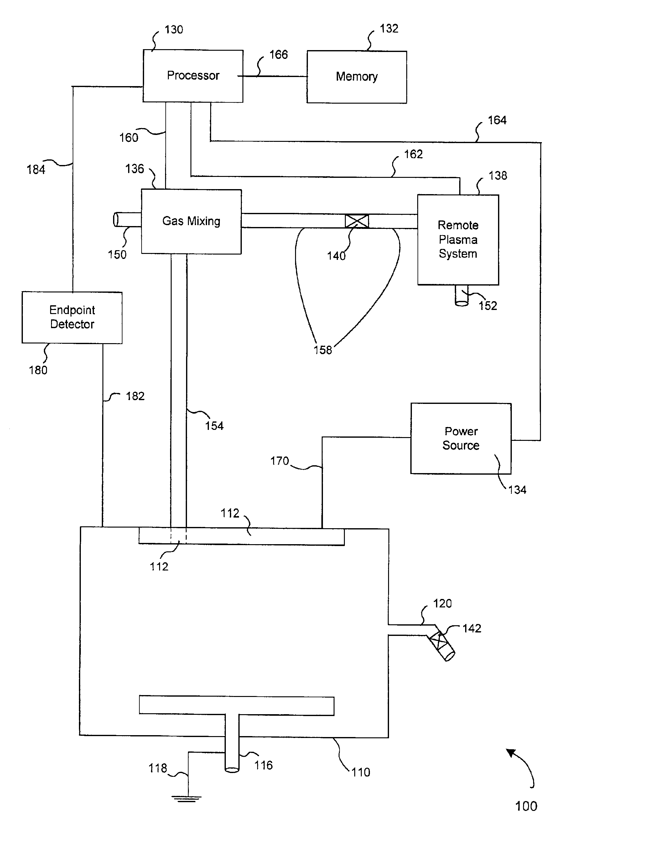
Elements of the present invention are described in relation to a diagram of a cleaning system 100 as illustrated in FIG. 1. Referring to FIG. 1, some embodiments of cleaning system 100 include an equipment to be cleaned 110, which in an embodiment is a process chamber used to process semiconductor substrates. Additionally, an embodiment of system 100 includes a processor 130, a processor memory 132, a local plasma system (described below), a gas mixing block 136, a remote plasma system 138, and an endpoint detector 180. Equipment to be cleaned 110 includes, but is not limited to, a faceplate 112, a faceplate orifice 114, a bottom faceplate 1...


PUM

PropertyMeasurementUnit
Efficiencyaaaaaaaaaa
Plasma poweraaaaaaaaaa

Abstract

Methods and apparatus for cleaning semiconductor processing equipment. The apparatus include both local and remote gas dissociators coupled to a semiconductor processing chamber to be cleaned. The methods include introducing a precursor gas into the remote dissociator where the gas is dissociated and introducing a portion of the dissociated gas into the chamber. Another portion of the dissociated gas which re-associates before introduction into the chamber is also introduced into the chamber where it is again dissociated. The dissociated gas combines with contaminants in the chamber and is exhausted from the chamber along with the contaminants.

Description

BACKGROUND OF THE INVENTIONThe present invention relates in general to methods and apparatus for cleaning semiconductor processing equipment, and in particular to remote equipment cleaning where the equipment is cleaned without exposure to the surrounding atmosphere.In general, manufacturing semiconductor devices involves many processing steps performed under extremely clean conditions using semiconductor processing equipment. At any of the processing steps, the manufactured device may be exposed to a seemingly small amount of contamination which may result in a defect to the device. For example, a contaminant particle as small as 100 Å in diameter can result in a fatal defect in a manufactured device. Thus, reducing contamination during semiconductor processing is directly related to device yield and, in turn, profits.The problem of contamination is exacerbated by the continual reduction in feature size and also by increasing wafer and die sizes. More specifically, decreasing featu...

Claims


Application Information

Patent Timeline
IPC IPC(8): B08B7/00C23C16/52C23C16/44H01J37/32
CPCB08B7/00C23C16/4405H01J37/32862C23C16/52Y10S134/902
Inventor NOWAK, THOMASLATCHFORD, IANTANAKA, TSUTOMUKIM, BOK HEONXU, PINGFOSTER, JASONDESHONG, HEATH B.SEAMONS, MARTIN
Owner APPLIED MATERIALS INC
Why Eureka
Try Eureka