Metal push belt and material therefor

a push belt and metal technology, applied in the direction of driving belts, v-belts, belts/chains/gearrings, etc., can solve the problems of unnecessarily expensive and complicated production, and achieve the effect of reducing the disadvantageous effect, good fatigue strength, and reducing the fatigue strength of a band

Inactive Publication Date: 2005-03-22
VAN DOORNES TRANSMISSIE BV
View PDF9 Cites 4 Cited by
  • Summary
  • Abstract
  • Description
  • Claims
  • Application Information

AI Technical Summary

Benefits of technology

Although the prescription from the latter publication undisputedly leads to an improved fatigue durability of steel, it is by the present invention found to be unduly strict for application in the field of push belts, and thereby unnecessarily expensive and complicated in production. The invention therefor aims at providing a material prescription for steel, in particular optimised for use in a push belt however without the pre-mentioned disadvantages, at least a prescription reducing the disadvantageous effects, preferably addressing a specific material fatigue requirement relating to a required at least virtually infinite number of revolutions to pass in a belt's life time.
, preferably addressing a specific material fatigue requirement relating to a required at least virtually infinite number of revolutions to pass in a belt's life time.
In accordance with the invention the features disclosed below achieve this. In accordance with the idea underlying the invention, this prescription is achieved by replacing the standard fatigue test of base material producers by an application based fatigue test incorporating the experience of the application of steel at the development and production of push belts and the process therefor. In this manner the fatigue durability is not attained by testing the material per se, rather it is attained by a test in which the specific material treatments required for achieving a push belt's band are taken account of in the test, and in which test are also incorporated the interaction of such tensile means with its environment in the push belt, and finally, it takes account of the exact and typical manner in which a tensile means is subjected to cyclically varying stresses when loaded during operation in a transmission.
In accordance with the latter approach according to the invention it was found that the critical process determining the life time of steel as effectively incorporated in a steel belt for CVT include the numerous amount of times of bending and stretching of the steel bands at rotating in a transmission, combined with stresses due to e.g. pressure contacts and relative movements of the bands mutually, and the tensile loading of the bands. An additional amount of stress is taken into consideration due to the bending of the belt when entering the circular trajectory in a pulley. Subsequent stretching of a band occurs when the band exits a pulley for crossing towards the other pulley in a straight trajectory part in between the pulleys. In the bent trajectory of a tensile means, the innermost and outermost band are not only loaded by a mutual band-band contact, but additionally loaded by friction with and Hertzian stress from contacting the saddle and ear respectively of the transverse elements. This led to the conclusion that the setting of a desired level of fatigue strength of a band can be addressed by influencing the material features per se. This differs from setting a nominal tensile strength of a band to a desired level, which can be done by relating the specific tensile strength of the belt material to the dimensions of the cross section of the belt.
From microscopic research it was found that the earlier mentioned local disruption in the material structure subsequently forms an initiation for material tearing, i.e. material crack, so that failure of a band occurs, i.e. is initiated invisibly by an inside factor rather than from an outside factor. Based on this insight various fatigue tests have been conducted under dynamic, i.e. rotating conditions, in particular with complete belt / pulley tests, showing that a good result in fatigue strength, related to the number and size distribution of inclusions is achieved as discussed below.
It was herewith favourably found that the steel could be produced according to a less strict prescription than the known prescription while still meeting the requirements prescribed by the actual application and use thereof in a push belt. Rather than when departing from the standardised fatigue tests from the field of materials it was thus found that the steel for push belts might be produced in a grade less expensive and complicated to produce than the material known from the prior art.

Problems solved by technology

Although the prescription from the latter publication undisputedly leads to an improved fatigue durability of steel, it is by the present invention found to be unduly strict for application in the field of push belts, and thereby unnecessarily expensive and complicated in production.

Method used


Image

  • Metal push belt and material therefor
  • Metal push belt and material therefor
  • Metal push belt and material therefor

Examples


Embodiment Construction

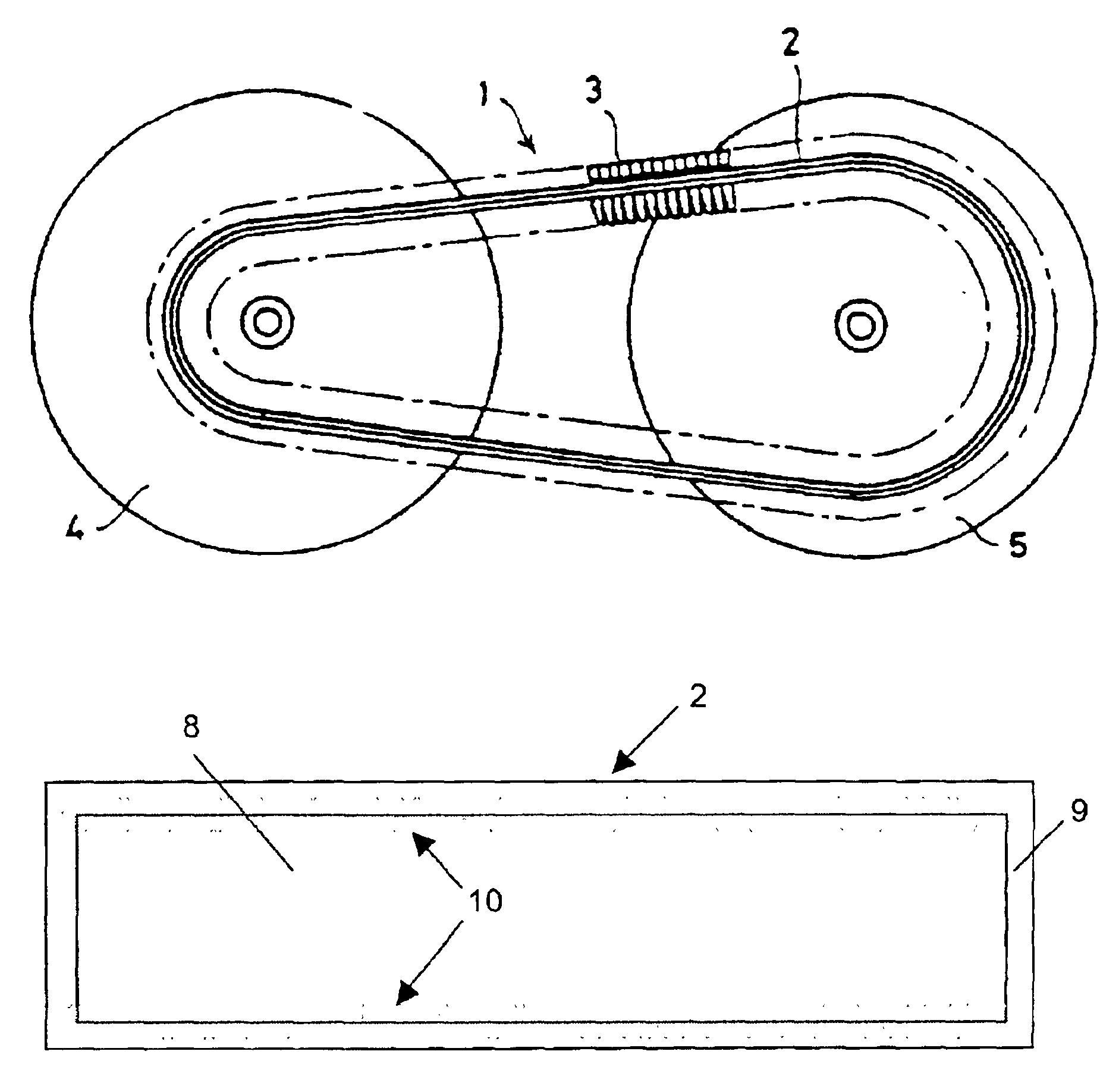
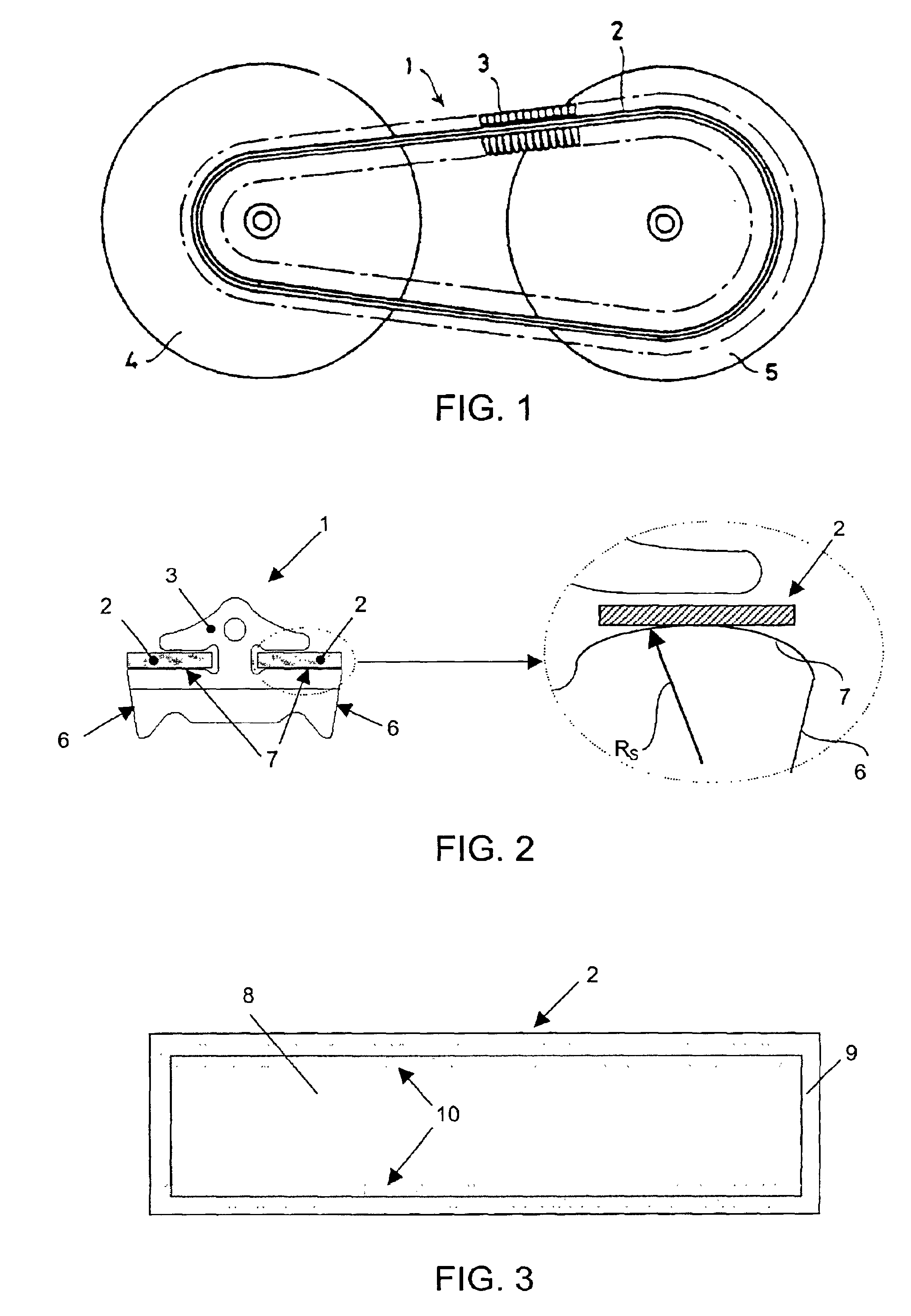
FIG. 1 shows schematically a continuous variable transmission (CVT) with a conveyor belt 1 which is made up of a tensile means 2 in the form of nested endless thin bands, and on which there are an endless continuous series of cross elements 3, alternatively denoted transverse elements, which slide freely there over. They move between the sheaves of pulleys 4 and 5, with steplessly variable diameter. Such a continuous variable transmission is known per se. Typical thickness of a band range from 0.15 to 0.25 mm. Typical widths of a band range from 8 to 35 millimeters. Typical circumferential lengths of a drive belt 1 range from 50 to 100 cm. For reasons of economical production and for preventing technical complexity, a belt usually runs between pulleys 4, 5 of which only one sheaf is arranged axially movable, while the other is arranged rotationally and axially fixed to an axle of rotation. This arrangement means that during operation the alignment of a belt 1 and its bands 2 deviate...


PUM

PropertyMeasurementUnit
diametersaaaaaaaaaa
inclusion diameteraaaaaaaaaa

Abstract

A metal push belt (1) for application in a continuous variable transmission, includes at least one endless tensile member (2), and transverse elements being provided freely moveable in the endless direction of the tensile member (2). The tensile member is produced of steel, containing non-metallic inclusions of predetermined sizes as observed in the micro-structure of a material section, in accordance with a specified diameter Dcircle of a circle relating to the surface occupation of such an inclusion observed in such micro structure, in which the steel is produced in a constitution having a nominal inclusion size distribution with diameters ranging up to 30 μm, the inclusion diameter range between 10 μm and 30 μm being less than 20% of the total number of inclusions per square unit of sliced material counted by inclusions having a size larger than 2 μm.

Description

BACKGROUND OF THE INVENTIONThe present invention relates to a metal belt for continuously variable transmissions as described below and to a material for such belt.DESCRIPTION OF THE RELATED ARTA belt for a continuous variable transmission is generally known, e.g. from EP-A0181670 or from U.S. Pat. No. 3,949,621. The belt comprises at least one endless metal band, preferably provided in a set of generally conforming nested bands, at least partly being surrounded by transverse elements for at least clamping the belt in between the sheaves of a set of pulleys.The bands of this known construction have a flat, generally rectangular cross section. Due to its nature of use in continuously variable transmissions, the known belt is during operation subjected to extremely high stresses varying in height with the radius of bending and with the belt speed and moment transmitted or the pull force in a band, i.e. the tensile means of the belt, resulting there from. For this reason avoidance of b...

Claims


Application Information

Patent Timeline
Patent Type & Authority Patents(United States)
IPC IPC(8): C22C38/00C22C38/12C22C38/08F16G5/00F16G5/16
CPCC22C38/001F16G5/16C22C38/12C22C38/08
Inventor PENNINGS, BERTVAN DEN BOOMEN, HENDRIKUSBRANDSMA, ARJEN
Owner VAN DOORNES TRANSMISSIE BV
Why Eureka
Try Eureka