Purification of carbon filaments and their use in storing hydrogen

a carbon filament and hydrogen storage technology, applied in the direction of single-walled nanotubes, chemistry apparatus and processes, textiles and paper, etc., to achieve the effect of high yield, and reducing the amount of amorphous carbon impurities

Inactive Publication Date: 2005-03-22
PENN STATE RES FOUND
View PDF5 Cites 19 Cited by
  • Summary
  • Abstract
  • Description
  • Claims
  • Application Information

AI Technical Summary

Benefits of technology

[0013]An advantage of the present invention is a facile method of obtaining carbon structures from an impure mixture in high yields.
[0014]Another advantage of the present invention is the synthesis of single-walled nano-tubes suitable for hydrogen storage.
[0015]Additional advantages and other features of the invention will be set forth in part in the description which follows and in part will become apparent to those having ordinary skill in the art upon examination of the following or may be learned from the practice of the invention. The advantages of the invention may be realized and obtained as particularly pointed out in the appended claims.
[0016]According to the present invention, the foregoing and other advantages are achieved in part by a process of reducing the amount of amorphous carbon from a carbon mixture. The process comprises heating an impure mixture containing amorphous carbon and at lest one crystalline form of carbon in the presence of an oxidizing gas at a temperature and time sufficient to selectively oxidize and reduce the amount of amorphous carbon impurities from the mixture. Advantageously, the present inventive process permits the purification of single-walled nano-tubes from relatively inexpensive, yet difficult to purify, arc-derived soot. These soots typically have a substantial amount of amorphous carbon as well as other undesirable carbon forms in addition to the desired carbon structures. These undesirable carbon forms can be reduced, i.e. lowered from their initial concentration of untreated material, by selective oxidation. Metal containing impurities can also be reduced or removed from the mixture by exposing the desired carbon structures and accompanying impurities to an acid to produce a carbon structure, e.g. carbon fiber, that is substantially free of the undesirable carbon, i.e. carbon impurities, and metal impurities. Additional processing steps can include heating the purified carbon structure under vacuum to anneal the carbon structure to ameliorate part or all of any defects that were formed in the carbon structure during the purification process or other wise.
[0017]Embodiments of the present invention include heating the impure carbon mixture in the presence of an oxidizing gas to a temperature from about 295° C. to about 500° C., e.g. from about 350° C. to about 410° C., to reduce carbon impurities, such as amorphous carbon and graphitic carbon covering metal containing impurities; removing metal containing impurities by exposing the impure mixture to an acid, e.g. nitric or hydrochloric acid, at a temperature from about 25° C. to about the boiling temperature of the acid.
[0018]Another aspect of the present invention is a process of purifying a carbon nano-fiber. The process comprises heating an impure mixture containing the carbon nano-fiber in the presence of an oxidizing gas, e.g. air, and at a temperature and time sufficient to selectively oxidize and reduce the amount of carbon impurities from the mixture. Metal containing impurities, e.g. metal catalyst and their salts, are reduced or substantially removed from the mixture by exposing the mixture to an acid, e.g. hydrochloric acid, to produce a carbon fiber reduced or substantially free of carbon impurities and metal containing impurities. The purified carbon-nano-fiber can then be subjected to heat, e.g. about 220° C. to about 1000° C., under a vacuum, e.g. between about 10−8 Torr to about 10−6 Torr, to ameliorate damage to the tubes caused by or in addition to the purification process.

Problems solved by technology

These soots typically have a substantial amount of amorphous carbon as well as other undesirable carbon forms in addition to the desired carbon structures.

Method used


Image

  • Purification of carbon filaments and their use in storing hydrogen
  • Purification of carbon filaments and their use in storing hydrogen
  • Purification of carbon filaments and their use in storing hydrogen

Examples


examples

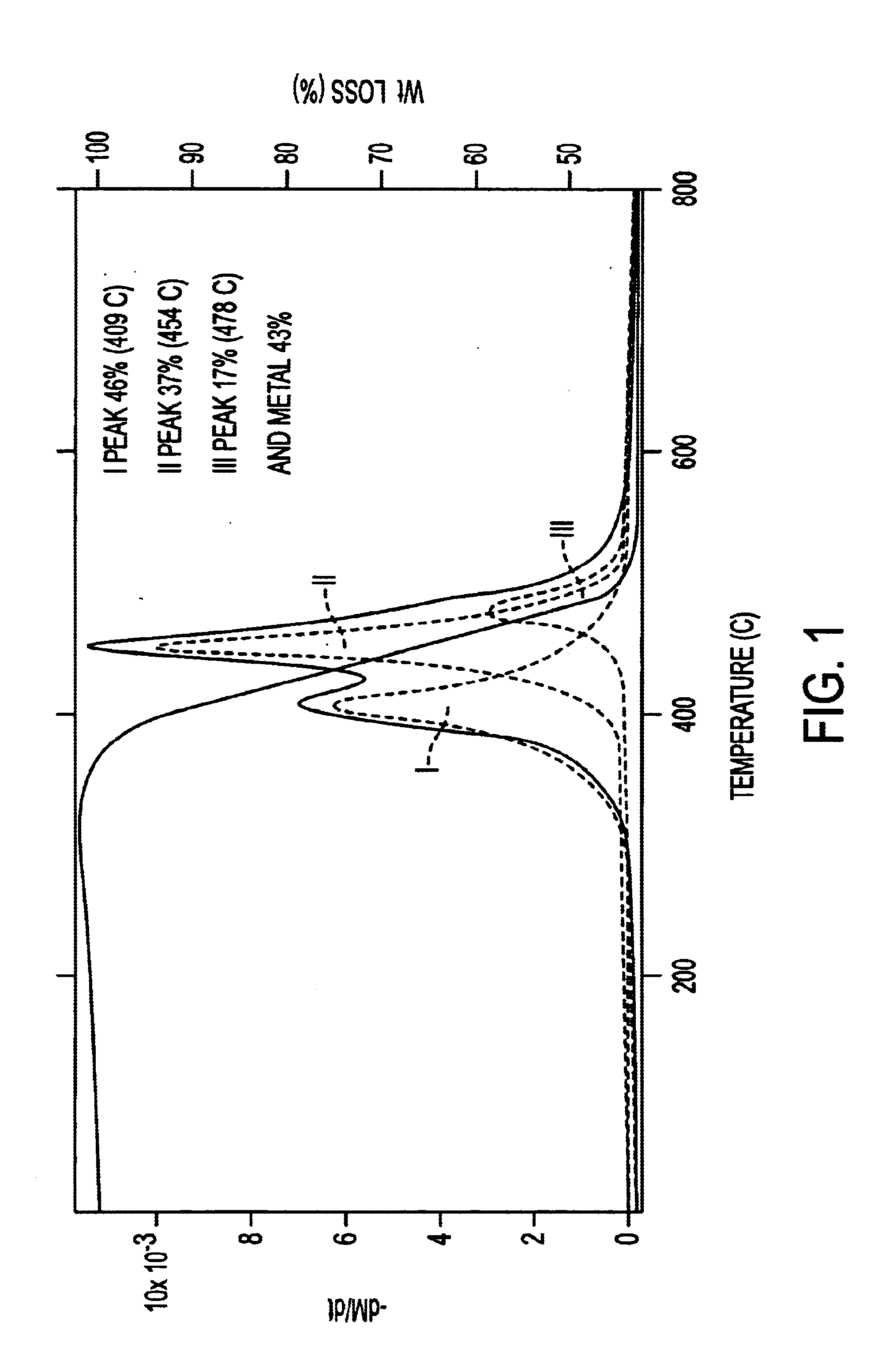
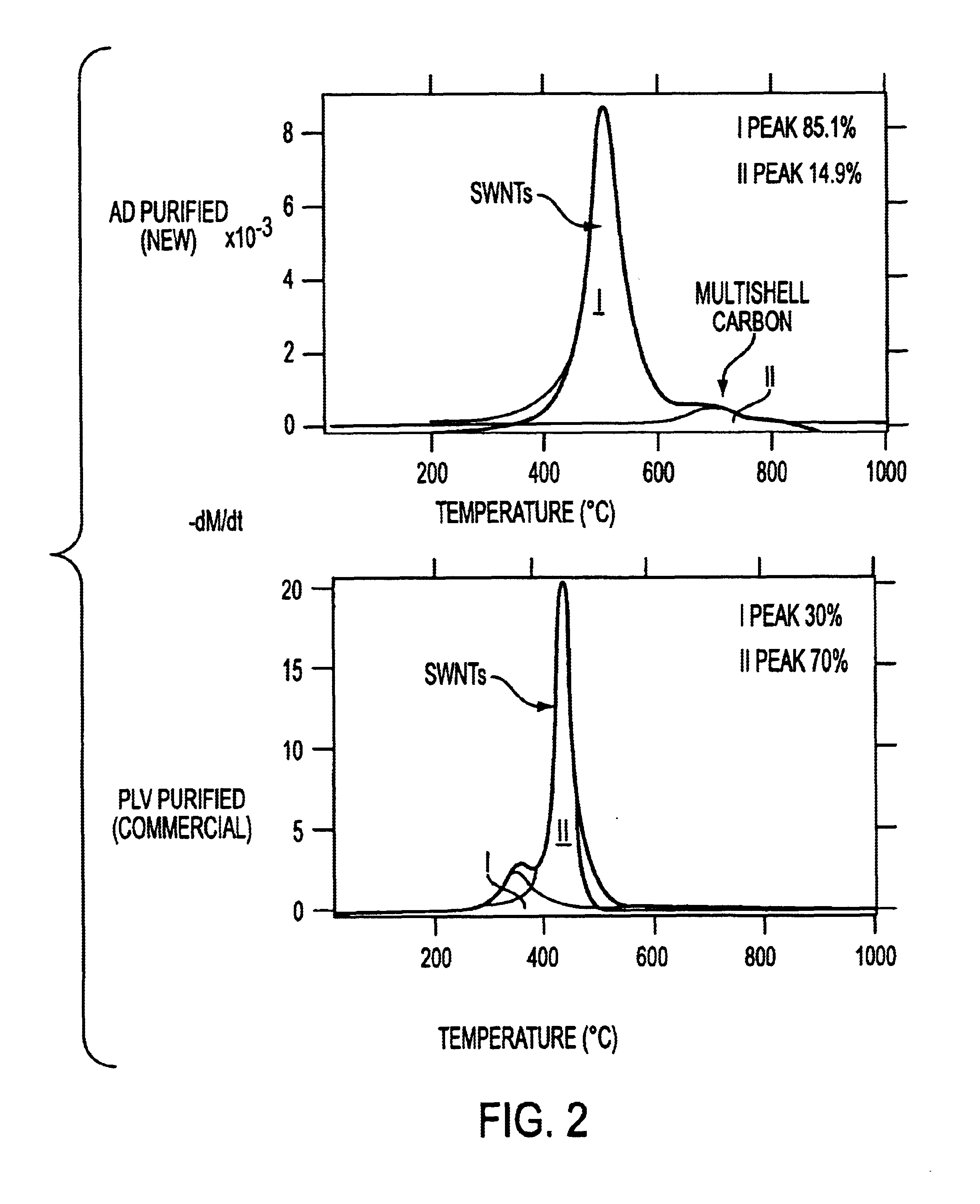
[0034]The raw soots produced by AD were prepared as described earlier (C. Journet et al., Nature vol 388, pp 756) and received as dry powders from Carbolex, Inc. of Lexington, Ky. Chemical analysis of these soots were carried out by temperature programmed oxidation (TPO) using a TG-50 Mettler thermogravimetric analyzer (TGA). The TGA reaction conditions included a 5° C. / min heating rate starting from about 25 C. and ending at about 1000° C. under a flow of dry air at about 100 sccm. From the first derivative of the TPO curve, or the DTPO curve, the preferential oxidation temperatures of the different phases of carbon in these soots were determined, as described below.

[0035]For purification, raw SWNT soot was selectively oxidized under conditions defined by the TPO results. The soot was then refluxed in hydrochloric acid (HCl) using standard Pyrex glassware for a few hours, and the suspension was then filtered through a polycarbonate membrane filter (pore size=1 μm, available from Co...


PUM

PropertyMeasurementUnit
temperatureaaaaaaaaaa

Abstract

Carbon structures, e.g. carbon nano-fibers, suitable for absorbing hydrogen at low pressures and low temperatures are produced by a selective oxidation and / or acid reflux process. The process includes heating an impure mixture containing a crystalline form of carbon in the presence of an oxidizing gas at a temperature and time sufficient to selectively oxidize and remove a substantial amount of any amorphous carbon impurities from the mixture. Metal containing impurities can be removed from the mixture by exposing the desired carbon and accompanying impurities to an acid to produce a carbon fiber that is substantially free of both non-fiber carbon impurities and metal impurities. Another aspect of the present invention includes purified carbon structures that can store hydrogen at low pressures and temperatures.

Description

CROSS-REFERENCE TO RELATED APPLICATIONS[0002]This application claims priority from U.S. Provisional Patent Application Serial No. 60 / 324,066 filed Sep. 24, 2001, entitled, “PURIFICATION OF CARBON FILAMENTS AND THEIR USE IN STORING HYRDOGEN” and U.S. Provisional Patent Application Serial No. 60 / 283,470 filed Apr. 12, 2001, entitled, “PURIFICATION OF CARBON FILAMENTS USSED FOR HYDROGEN STORAGE AT LOW PRESSURE AND CRYOGENIC TEMPERATURE” the entire discloses of which are incorporated herein by reference.FIELD OF THE INVENTION[0003]The present invention relates to carbon filaments and processes for their production and more particularly to a process for obtaining purified single-walled nanotubes these materials have utility in the fields of chemistry, drugs, electronics, transportation, among others.BACKGROUND[0004]Single-wall carbon nanotubes (SWNTs) were reported simultaneously by Iijima and co-workers at NEC and by Bethune and co-workers at IBM as early as 1993. The structure of a SWN...

Claims


Application Information

Patent Timeline
Patent Type & Authority Patents(United States)
IPC IPC(8): C01B3/00C01B31/00C01B31/02D01F9/12D01F9/127
CPCB82Y30/00B82Y40/00C01B3/001C01B3/0021D01F9/12C01B31/026Y10S977/848C01B2202/02Y02E60/325Y02E60/327C01B32/17Y02E60/32
Inventor HARUTYUNYAN, AVETIKPRADHAN, BHABENDRAEKLUND, PETER C.FUJIWARA, YOSHIYAGOTO, HAJIME
Owner PENN STATE RES FOUND
Why Eureka
Try Eureka