
Power supply control system for heater used in gas sensor

a technology of power supply control and gas sensor, which is applied in the direction of electrical control, instruments, material electrochemical variables, etc., can solve the problems of lowering gas concentration sensor usually undergoes an undesirable change in power supply, and electric noises to be added to the harness, so as to minimize the error in determining and improve the controllability of the power supply to the heater

Inactive Publication Date: 2005-03-22
DENSO CORP
View PDF8 Cites 25 Cited by
  • Summary
  • Abstract
  • Description
  • Claims
  • Application Information

AI Technical Summary

Benefits of technology

It is another object of the present invention to provide a heater control system for gas concentration sensors which is designed to determine a controlled variable properly used to control a heater built in the gas concentration sensor, thereby resulting in improved controllability of a power supply to the heater.
It is a further object of the invention to provide a heater control system for gas concentration sensors which works to minimize an error in determining the resistance of a heater built in the gas concentration sensor.
The control circuit works to supply power to the heater in a cycle and controls an on-time for which the power is supplied to the heater. The control circuit allows the heater control variable correcting circuit to determine one of a heater voltage developed at the heater and a current flowing through the heater which is employed to determine the heater power consumed in the heater only when the on-time is longer than a given reference value.
In the preferred mode of the invention, the apparatus also includes a guard value providing means for providing a guard value which works to define a limit of the heater control variable. The guard value is increased with an increase in the resistance value of the sensor element determined by the sensor element resistance determining circuit.
The control circuit works to supply power to the heater in a cycle and controls an on-time for which the power is supplied to the heater. The control circuit allows the heater control variable correcting circuit to determine one of a heater voltage developed at the heater and a current flowing through the heater which is employed to determine the heater power consumed in the heater only when the on-time is longer than a given reference value.
According to the third aspect of the invention, there is provided a gas concentration sensor control apparatus comprising: (a) a gas concentration sensor having a solid electrolyte-made sensor element producing a sensor output indicative of a concentration of a specified gas component: (b) a heater installed in the gas concentration sensor to heat the sensor element up to a temperature at which the sensor element is activated to produce the sensor output correctly; (c) a heater power supply control circuit working to turn on and off a power supply to the heater cyclically; (d) a sensor element resistance determining circuit working to measure a resistance value of the sensor element in a cycle by changing one of a voltage applied to the heater and a current flowing through the heater instantaneously, monitoring a change in the one of the voltage and the current, and calculating the resistance value as a function of the change; (e) a heater control variable determining circuit determining a heater control variable, which is used in the heater power supply control circuit to define an on-time for which the power supply to the heater is to be turned on and an off-time for which the power supply to the heater is to be turned off, as a function of a difference between the resistance value determined by the sensor element resistance determining circuit and a target value; and (f) a control circuit determining whether an on-off switching time at which the power supply to the heater is to be switched on or off will overlap with a measurement time for which the resistance value is to be measured. When it is determined that the on-off switching time will overlap with the measurement time, the control circuit shifts one of the on-off switching time and the measurement time. This enables the resistance value to be determined correctly without addition of an electric noise arising from the on-off switching of the power supply to the heater.

Problems solved by technology

The gas concentration sensor usually undergoes an undesirable change in power supply due to a drop in voltage applied to the heater through a harness and / or a change in output voltage of a power source.
This results in lowered controllability of the power supply to the heater.
Further, switching between on-time and off-time of the duty cycle of the pulse signal usually cause electric noises to be added to the harness coupled to the heater.
Therefore, if such switching overlaps with a period of time during which the resistance of the sensor element is measured, it may result in an error in measuring the resistance of the sensor element.
This problem is encountered frequently, especially in a case where harnesses leading to the sensor element and to the heater are tied together.

Method used


Image

  • Power supply control system for heater used in gas sensor
  • Power supply control system for heater used in gas sensor
  • Power supply control system for heater used in gas sensor

Examples


first embodiment

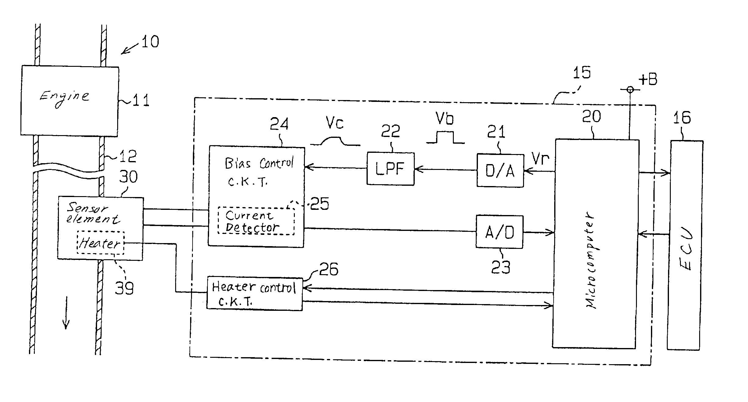
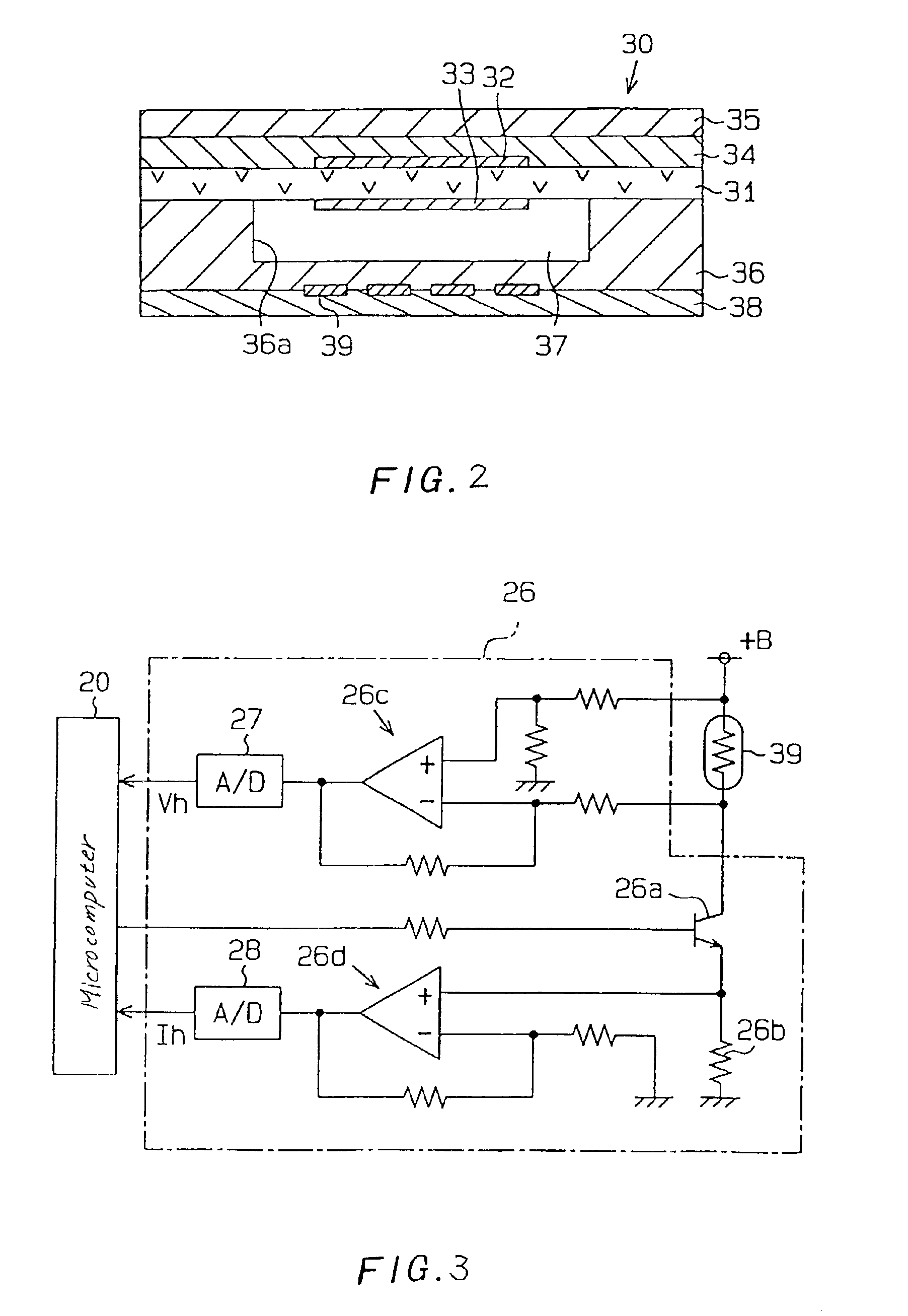
Referring now to the drawings, wherein like numbers refer to like parts in several views, particularly to FIG. 1, there is shown a gas sensor control system according to the invention which is installed in an air-fuel ratio measuring device 15 used with an air-fuel ratio control system for automotive vehicles. The air-fuel ratio control system is designed to control the quantity of fuel injected into an internal combustion engine as a function of an output of the air-fuel ratio measuring device 15 under feedback (F / B) control to bring the air-fuel ratio into agreement with a target value. The air-fuel ratio measuring device 15 measures the concentration of oxygen (O2) contained in exhaust gasses of the engine using an output of a limiting current oxygen sensor 30 (will be referred to as an A / F sensor below) and determines an air-fuel ratio. The air-fuel ratio measuring device 15 also has installed therein a heater control system which works to determine the impedance of a sensor ele...

second embodiment

FIG. 11 shows an air-fuel ratio measuring device 15 which is designed to measure the concentration of NOx as well as O2 contained in exhaust gasses of the engine.

The air-fuel ratio measuring device 15 includes a gas concentration sensor 100 that is of a so-called composition type having, as shown in FIGS. 12(a) and 12(b), a three-cell structure to measure the concentration of NOx and O2 simultaneously.

The gas concentration sensor 100 includes generally solid electrolyte plates 141 and 142 made of an oxygen ion-conducting material. The solid electrolyte plates 141 and 142 are laid to overlap each other at a given interval through a spacer 143 made of an insulating material such as alumina. The solid electrolyte plate 141 has formed therein a pinhole 141a through which exhaust gasses flowing around the gas concentration sensor 100 are admitted into a first chamber 144. The first chamber 144 communicates with a second chamber 146 through an orifice 145 working as a diffusion path. On ...


PUM

PropertyMeasurementUnit
porosityaaaaaaaaaa
frequencyaaaaaaaaaa
impedance ZACaaaaaaaaaa

Abstract

A heater control system is provided for controlling the temperature of a heater used to heat a solid electrolyte-made sensor element of a gas concentration sensor up to a given temperature at which the sensor element is activated to provide a correct gas concentration output for controlling a preselected variable used in, for example, an automotive air-fuel ratio control system. The heater control system measures a resistance value of the sensor element and controls an electric power supplied to the heater as a function of the resistance value. The heater control system is designed to determine a controlled variable properly used to control the heater, thereby resulting in improved controllability of a power supply to the heater and also works to minimize an error in determining the resistance of the heater.

Description

BACKGROUND OF THE INVENTION1. Technical Field of the InventionThe present invention relates generally to a power supply control system for a heater working to heat a gas sensor such as a gas concentration sensor up to a desired activation temperature which may be employed in an air-fuel ratio control system for automotive vehicles for measuring the concentration of a specified component such as O2, NOx, or CO contained in exhaust emissions from the engine.2. Background ArtAir-fuel ratio control for automotive internal combustion engines is typically accomplished using an output of a gas concentration sensor. Such a gas concentration sensor has a sensor element which includes a solid electrolyte member made of zirconia. The sensor element works to measure the concentration of a given gas component (e.g., oxygen) of exhaust gasses of the engine. An air-fuel ratio control system determines an air-fuel ratio as a function of the measured concentration of the gas component. Ensuring the ...

Claims


Application Information

Patent Timeline
Patent Type & Authority Patents(United States)
IPC IPC(8): F02D41/14G01N27/406H05B1/02G01N27/41G01N27/416G01N27/419
CPCF02D41/1494H05B1/0236G01N27/4067
Inventor HADA, SATOSHIKUROKAWA, EIICHINIWA, MITSUNOBU
Owner DENSO CORP
Learn More