Variable cam timing unit oil supply arrangement

a timing unit and cam timing technology, which is applied in the direction of machines/engines, mechanical equipment, auxilaries, etc., can solve the problems of parasitic losses and fuel economy degradation across the entire engine speed range, low idle speed (500 rpm) and ever lower lug limits, and achieve high engine oil pressure and high flow rate. , the effect of preventing undesired noise of vibration

Inactive Publication Date: 2005-03-29
FORD GLOBAL TECH LLC
View PDF11 Cites 35 Cited by
  • Summary
  • Abstract
  • Description
  • Claims
  • Application Information

AI Technical Summary

Benefits of technology

The present invention incorporates a small, on-demand auxiliary oil pump in conjunction with an accumulator chamber arranged via check valving to supply the VCT unit. Accordingly, there is no additional requirement for pressurized oil flow to the remainder of the engine and the main engine oil pump supplies the VCT unit and also pumps up the accumulator when the engine speed is adequate to produce the high engine oil pressure needed for VCT operation. The accumulator allows short duration, high flow rate pulses needed to shift the VCT without having to size the main engine oil pump for a constant high flow rate. The present inventive engine arrangement allows little or no modification to existent oil pump energy requirements and enables instantaneous short duration, high flow pulses for activation of up to four VCT units. The present invention supplies adequate oil pressure to permit VCT activation at very low engine speeds (for example, a tip-in from a 500 rpm idle). The present invention also enables the VCT unit to return to the locked start-up position during cranking (important for stability and the prevention of undesired noise of vibration) should the engine inadvertently stall before achieving the locked position (non-normal shutdown situation). This failsafe ability is required for all VCT units that return to a stop in the advancing direction against normal valve train friction torque.

Problems solved by technology

Typically, the engine oil pump in most vehicles cannot meet the oil pressure instantaneous flow requirements of a VCT, especially at low engine speeds and high oil temperatures.
The increase in flow rate brings a disadvantage of parasitic losses and fuel economy degradation across the entire engine speed range.
Since the oil pump pressure requirements are most difficult to meet at low engine speeds and high oil temperatures, a major issue exists with low (500 rpm) idle speeds and ever lower lug limits (as low as 900 rpm with a continuously variable transmission).
At these conditions, the prior art approach of increasing the oil pump size will not meet the VCT unit demands, particularly with an engine having dual independent valve systems which require four VCT units for a V-type engine (one inlet valve camshaft, one outlet valve camshaft for each engine bank).
However, Scheidt et al. does not reveal an arrangement to meet the oil pump pressure requirements at low engine speed and high oil temperatures.

Method used


Image

  • Variable cam timing unit oil supply arrangement
  • Variable cam timing unit oil supply arrangement
  • Variable cam timing unit oil supply arrangement

Examples


Embodiment Construction

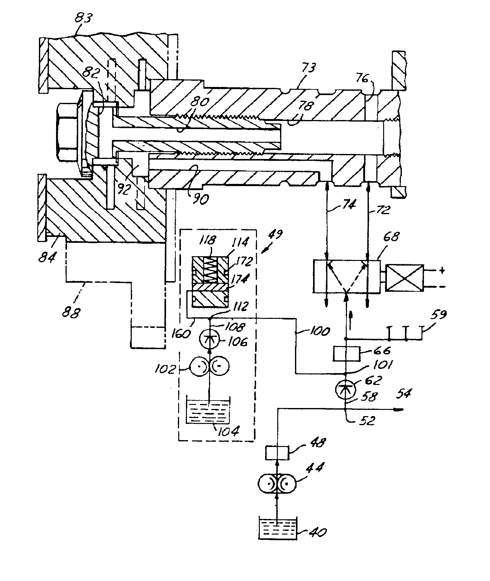
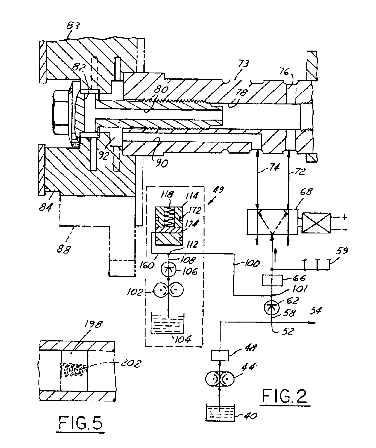
Referring to FIG. 2, a VCT oil supply arrangement 49 according to the present invention has a sump 40. The sump 40 is fluidly connected with a first or main engine oil pump 44. The main engine oil pump 44 in most applications is powered by the engine crankshaft (not shown) and delivers pressurized oil to and through a filter 48. In other embodiments, the engine oil pump may be electrically powered by a motor.

After leaving filter 48, pressurized oil is then delivered to a T connection 52. At lower engine speeds, virtually all the oil goes through line 54 to accommodate the various lubrication functions of the engine. Oil is also delivered to line 58. Line 58 is connected to an intake of a first check valve 62. Oil passing through check valve 62 passes through a VCT oil filter 66. Oil passing through filter 66 is delivered to solenoid valve 68. Oil from solenoid valve 68 may be delivered or removed into an intake camshaft 73, lines 72 and 74. Line 72 connects to a first passage that i...


PUM


Abstract

An internal combustion engine arrangement 7 with a variable cam timing unit pressurized oil supply arrangement 49 is provided. A first pump 44 delivers oil through a first check valve 62 to a VCT unit 83 and additionally provides oil to the engine lubrication system. A second oil pump 104 provides pressurized oil to the VCT unit 83 through a second check valve 106. An accumulator 114 is connected between the first 62 and second 106 check valves to pressurize oil delivered to the variable cam timing unit 83.

Description

BACKGROUND OF INVENTIONThis invention relates to an automotive vehicle with an internal combustion engine having a variable cam timing unit (VCT), and in particular to an arrangement of a pressurized fluid supply for a VCT of an automotive vehicle internal combustion engine.Automotive vehicle engines with reciprocal pistons typically have a plurality of cylinder combustion chambers with the reciprocating pistons mounted therein. Each piston is pivotally connected with a piston rod, which is pivotally connected with a crankshaft. A timing gear is mounted at an end of the crankshaft. Typically, each cylinder has at least one intake valve and one exhaust valve. Both the intake valve and the exhaust valve are spring-loaded to a closed position. Each intake and exhaust valve is associated with a rocker arm. To operate the valves, the rocker arms are moved by a set of contacting cam lobes. The cam lobes are mounted on an elongated member known as a camshaft. Attached at an extreme end of ...

Claims


Application Information

Patent Timeline
Patent Type & Authority Patents(United States)
IPC IPC(8): F01L1/344F01L1/34F01M1/12F01M1/00
CPCF01L1/022F01L1/34F01L1/024F01L2001/0475F01L2001/0476F01M2001/123F01L2001/34423F01L2001/3443F01L2001/3444F01L2001/34446F01L2001/34453F01L2001/0537
Inventor AIMONE, MICHAEL GEORGE
Owner FORD GLOBAL TECH LLC
Why Eureka
Try Eureka